Eureka AIR delivers breakthrough ideas for toughest innovation challenges, trusted by R&D personnel around the world.

Thermoluminescent reader system

Inactive Publication Date: 2006-06-22
UNITED STATES OF AMERICA THE AS REPRESENTED BY THE SEC OF THE ARMY
View PDF19 Cites 4 Cited by
  • Summary
  • Abstract
  • Description
  • Claims
  • Application Information

AI Technical Summary

Benefits of technology

[0028] Accordingly, one object of the present invention is to provide a TLD reader system that realizes consistent and accurate reader performance;
[0030] Still another object of the present invention is to provide a TLD reader system which allows for a hardened solid state design so as to be reliable and durable in field operations.
[0032] An infrared sensor senses the temperature of the thermoluminescent material and monitors the heating profile of the thermoluminescent material. The infrared sensor is connected to a CPU. The infrared sensor operates in a different waveband than the emission spectrum of the laser diode so as to prevent signal distortion.

Problems solved by technology

Some of the problems include measurement variation between readers, an inadequate badge temperature monitoring system, the requirement to operate in the frequency counting mode at high radiation levels, and variations in energy levels used to heat the badge elements.
Both techniques are plagued by heating profile problems as well as the inability to stabilize the output of the heating source.
Both heat lamp and compressed gas systems require photon counting at low radiation levels and frequency counting at higher radiation levels resulting in significant non-linearity problems.
The resultant saturation of photons at higher energy levels has created significant signal interpretation problems in prior art systems.
A number of problems have been recognized with the prior art TLD reader system of FIG. 1.
The tungsten lamp used as the heating mechanism, in conjunction with the silicon filter, is inefficient resulting in a considerable amount of wasted heat.
In addition the allowed tolerances in lamp power lead to variations in the heating profiles of the badge elements, and the use of the flux sensor has proven unreliable in determining the temperature of badge elements.
Still further, in that the emission of badge elements is hemispherical in nature, the emission geometry of the emitted photons has not been properly taken into account in the design of prior art photon collectors.
The result has been significant signal loss and inefficiency.
Operation in the frequency counting mode results in a reduction in measurement accuracy.
Further, the prior art optical design is not hardened for purposes of field operations and would be unlikely to be able to support deployable missions.

Method used


Image

  • Thermoluminescent reader system
  • Thermoluminescent reader system
  • Thermoluminescent reader system

Examples


Embodiment Construction

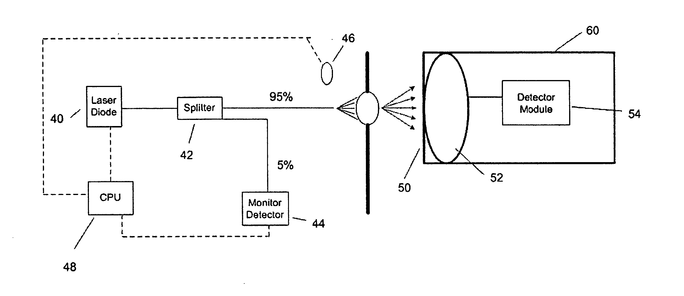
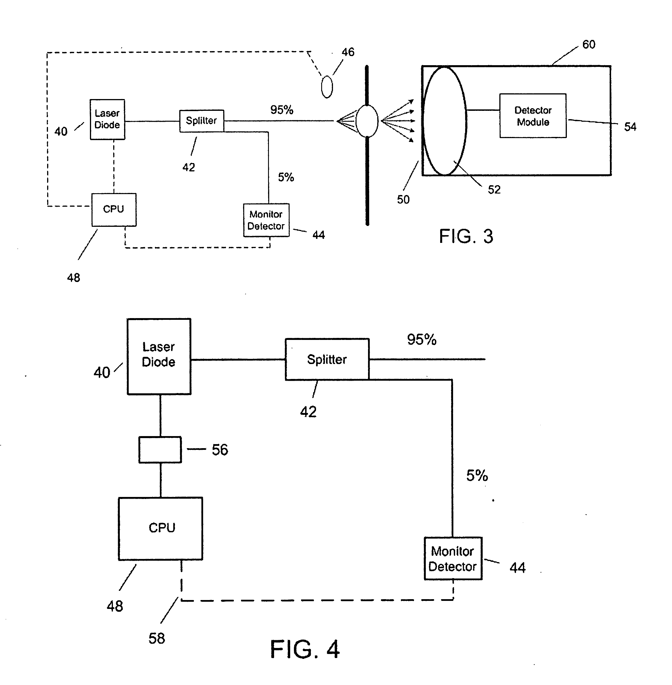
[0044] Referring now to the drawing wherein like numbers represent like parts in each of the several figures, FIG.3 demonstrates a fiber pigtailed laser diode 40 connected by fiber cable to a splitter 42. The splitter 42 directs a predetermined percentage of the power from the laser diode 40 to heat a TL material or badge element 14 while a remaining percentage of power is channeled to a monitor detector or evaluation un

[0045] An infrared sensor 46 is connected to CPU 48. The infrared sensor 46 monitors the badge TL element 14 substrate temperature to ensure that all badge elements are heated to the same temperature. In so doing, the infrared sensor effectively helps to ensure a uniform heating profile of the badge elements. The analog output (mV / DEG C) from the infrared sensor is correlated by the CPU 48 with individual badge elements so that changes in the badge element correction factors can be evaluated. The infrared sensor is selected to have a field a view which is sufficient...


PUM


Abstract

A TLD reader system has a laser diode that heats a thermoluminescent material causing a hemispherical photon emission that is collected by a ball lens. A filter ensures the ball lens receives and collects a predetermined transmittance value of the photons emitted within a predetermined range of wavelength. The ball lens sends the collected photons via a fiber-optic connection to a detection module. An infrared sensor senses the temperature and monitors the heating profile of the thermoluminescent material. A computer-controlled feedback loop maintains a constant output power from the laser diode.

Description

[0001] The invention described herein may be manufactured, used and licensed by or for the U.S. Government for governmental purposes without the payment of any royalties thereon.BACKGROUND OF THE INVENTION [0002] 1. Field of the Invention [0003] The present invention pertains to devices that measure the quantity of radiation to which an entity has been exposed. More particularly the present invention pertains to a reading system for ascertaining the amount of radiation received by a thermoluminescent material. Thermoluminescent materials are materials which emit light upon being heated. [0004] 2. Discussion of the Background [0005] By providing an individual or object with a thermoluminescent (TL) material, e.g., a badge containing a TL material, the radiation exposure of the individual or object can be determined. When TL materials are exposed to a source of ionizing radiation, electrons are freed. The release of the emancipated electrons results in positive charges remaining in th...

Claims


Application Information

Patent Timeline
IPC IPC(8): G01T1/11
CPCG01T1/115
Inventor FLOURNOY, JAMES T.HARRIS, WILLIAM S. JR.
Owner UNITED STATES OF AMERICA THE AS REPRESENTED BY THE SEC OF THE ARMY
Why Eureka
Eureka Blog
Learn More