Method and apparatus for chip cooling using a liquid metal thermal interface

a technology of thermal interface and liquid metal, which is applied in the direction of electrical apparatus, semiconductor devices, semiconductor/solid-state device details, etc., can solve the problems of thermal runaway, limited thermal conductivity of conventional pastes, and only practical for use with relatively low-power ic chips, etc., to facilitate the adhesion of liquid metal materials and good wetting

Inactive Publication Date: 2006-06-22
GLOBALFOUNDRIES INC
View PDF3 Cites 23 Cited by
  • Summary
  • Abstract
  • Description
  • Claims
  • Application Information

AI Technical Summary

Benefits of technology

[0008] In one embodiment, the present invention is a method and apparatus for chip cooling using a liquid metal thermal interface. One embodiment of an inventive thermal interface for facilitating thermal contact between opposing surfaces of an integrated circuit chip and a heat sink the thermal interface includes a liquid metal layer comprising a thermally conductive liquid metal material. A first supplemental layer bonds the liquid metal layer to the surface of the integrated circuit chip, and a second supplemental layer bonds the liquid metal layer to the surface of the heat sink. The first and second supplemental layers are adapted to facilitate adhesion of the liquid metal material to the integrated circuit chip and / or to the heat sink, as well as to provide good wetting with respect to the liquid metal material and to provide a barrier that isolates the liquid metal material from the integrated circuit chip and / or heat sink materials. In some embodiments, the first and second supplemental layers can be composite such that they are formed of two or more sub-layers.

Problems solved by technology

Such conductive pastes have generally proven to be reliable in facilitating heat transfer; however, the thermal conductivity of conventional pastes is typically limited (e.g., typical pastes have a thermal resistance of approximately 10 to 100 mm2-° C. / W).
Thus, these pastes are only practical for use with relatively low-power IC chips.
Moreover, heavy thermal cycling may cause non-uniform behavior in conventional pastes, or may cause conventional pastes to fail to thermally bond the chip to the heat sink, resulting in thermal run-away and also limiting chip cooling.

Method used


Image

  • Method and apparatus for chip cooling using a liquid metal thermal interface
  • Method and apparatus for chip cooling using a liquid metal thermal interface
  • Method and apparatus for chip cooling using a liquid metal thermal interface

Examples


Embodiment Construction

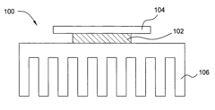
[0014] In one embodiment, the present invention is a liquid metal thermal interface that facilitates improved thermal contact between a semiconductor device (e.g., an IC chip) and a heat sink over conventional conductive paste interfaces. The thermal interface is assembled in a manner that substantially prevents reactions between materials in the liquid metal and materials in the IC chip and / or heat sink (e.g., such as corrosion of heat sink materials), as well as adheres the liquid metal to the surfaces of the IC chip and / or heat sink and achieves sufficient wetting of the IC chip and heat sink surfaces (wetting of the IC chip more significant than wetting of the heat sink in many embodiments). Thus, the thermal interface of the present invention makes deployment of the liquid metal a practical interface solution.

[0015]FIG. 1 is a schematic diagram illustrating one embodiment of a system 100 in which a thermal interface 102 according to the present invention is deployed. As illust...


PUM


Abstract

In one embodiment, the present invention is a method and apparatus for chip cooling using a liquid metal thermal interface. One embodiment of an inventive thermal interface for facilitating thermal contact between opposing surfaces of an integrated circuit chip and a heat sink the thermal interface includes a liquid metal layer comprising a thermally conductive liquid metal material. A first barrier layer bonds the liquid metal layer to the surface of the integrated circuit chip, and a second barrier layer bonds the liquid metal layer to the surface of the heat sink.

Description

CROSS REFERENCE TO RELATED APPLICATIONS [0001] This application claims the benefit of U.S. Provisional Patent Application Ser. No. 60 / 637,100, filed Dec. 17, 2004 by Furman et al. and U.S. Provisional Patent Application Ser. No. 60 / 637,117, also filed Dec. 17, 2004 by Furman et al., both of which are herein incorporated by reference in their entireties.REFERENCE TO GOVERNMENT FUNDING [0002] The present invention was made with Government support under Contract No. H98230-04-C-0920, awarded by the Maryland Procurement Office. The Government has certain rights in this invention.BACKGROUND [0003] The invention relates generally to integrated circuits, and relates more particularly to the cooling of integrated circuit chips. Specifically, the present invention relates to a thermal interface for chip cooling. [0004] Efficient cooling of integrated circuit (IC) devices is essential to prevent failure due to excessive heating. Efficient cooling of the IC chips depends in large part on good ...

Claims


Application Information

Patent Timeline
IPC IPC(8): H01L23/34
CPCH01L23/3736H01L23/3737H01L23/42H01L2924/0002H01L2924/00
InventorFURMAN, BRUCE K.GELORME, JEFFREY D.LABIANCA, NANCY C.MARTIN, YVES C.SHIH, DA YUANVAN KESSEL, THEODORE G.
OwnerGLOBALFOUNDRIES INC