Duplexer

Active Publication Date: 2006-06-22
TAIYO YUDEN KK
View PDF8 Cites 21 Cited by
  • Summary
  • Abstract
  • Description
  • Claims
  • Application Information

AI Technical Summary

Benefits of technology

[0018] Thus, the present invention can provide a duplexer that can maintain high isolation between signals and stable characteri

Problems solved by technology

With dielectric duplexers, it is difficult to obtain a smaller or thinner mobile terminal, because of the large size of each dielectric duplexer.
Even in a case where a surface acoustic wave device is employed, the size of a dielectric device makes it difficult to obtain a smaller or thinner mobile terminal.
Accordingly, the duplexer disclosed in J

Method used


Image

  • Duplexer
  • Duplexer
  • Duplexer

Examples


first embodiment

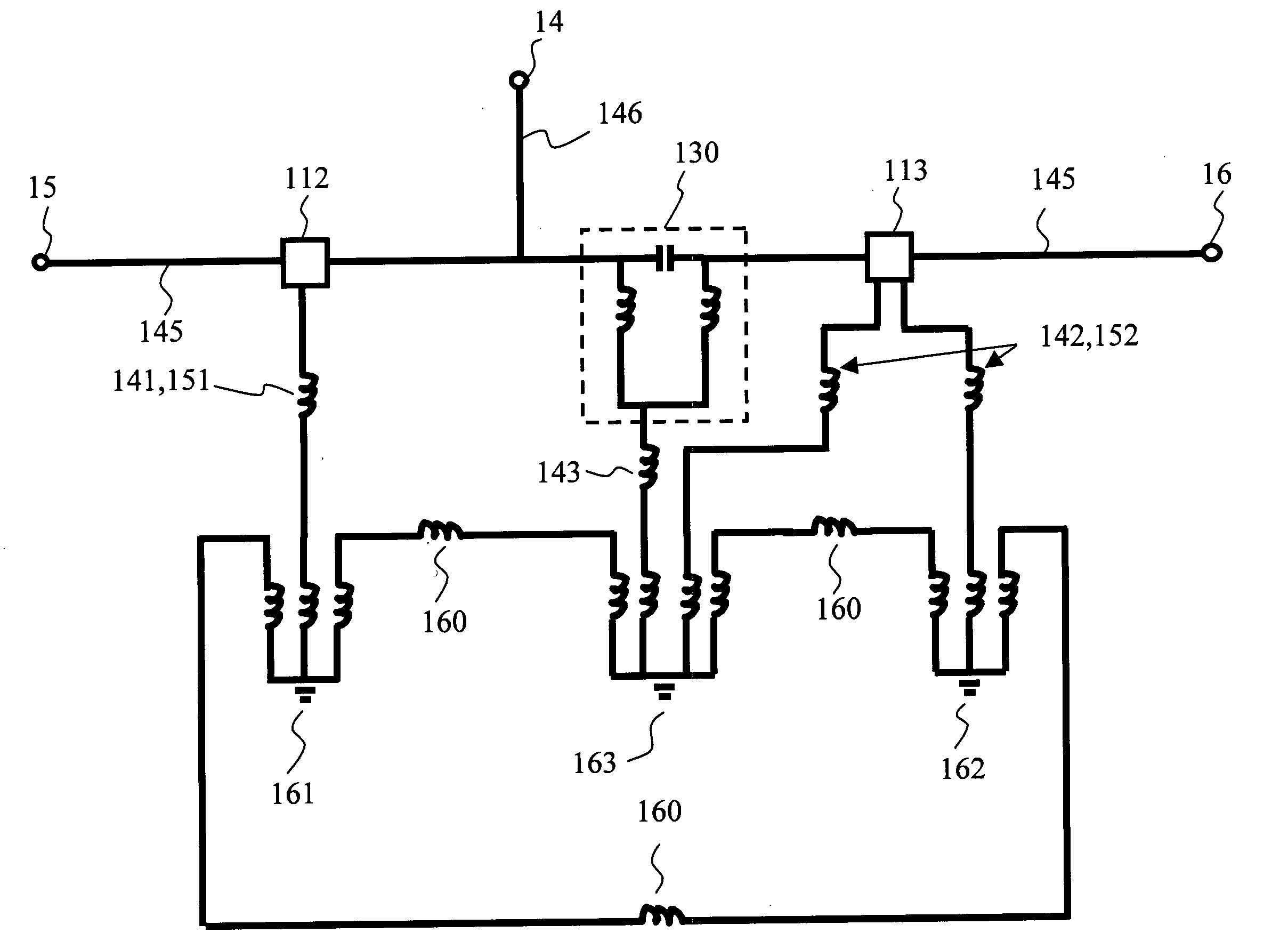
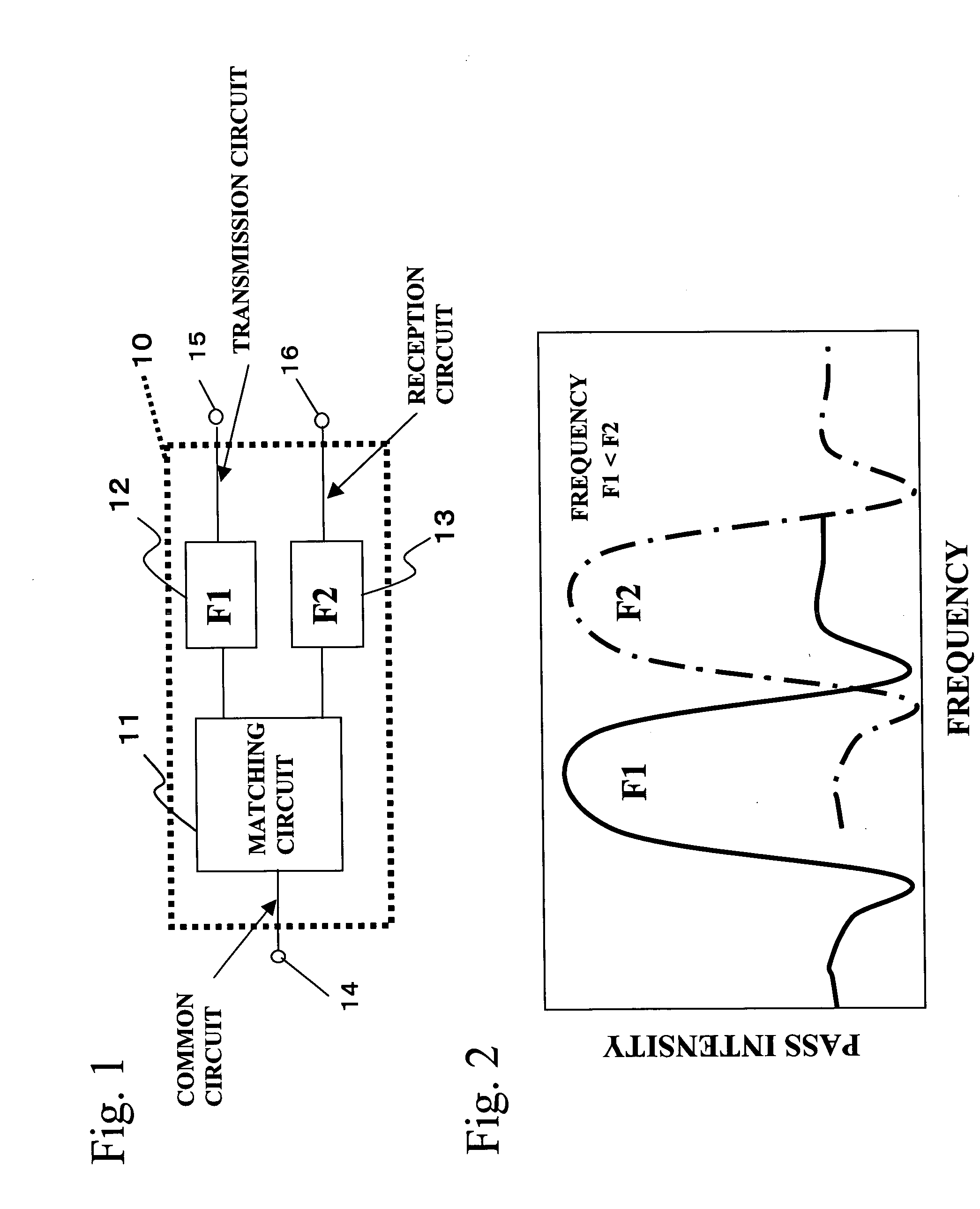
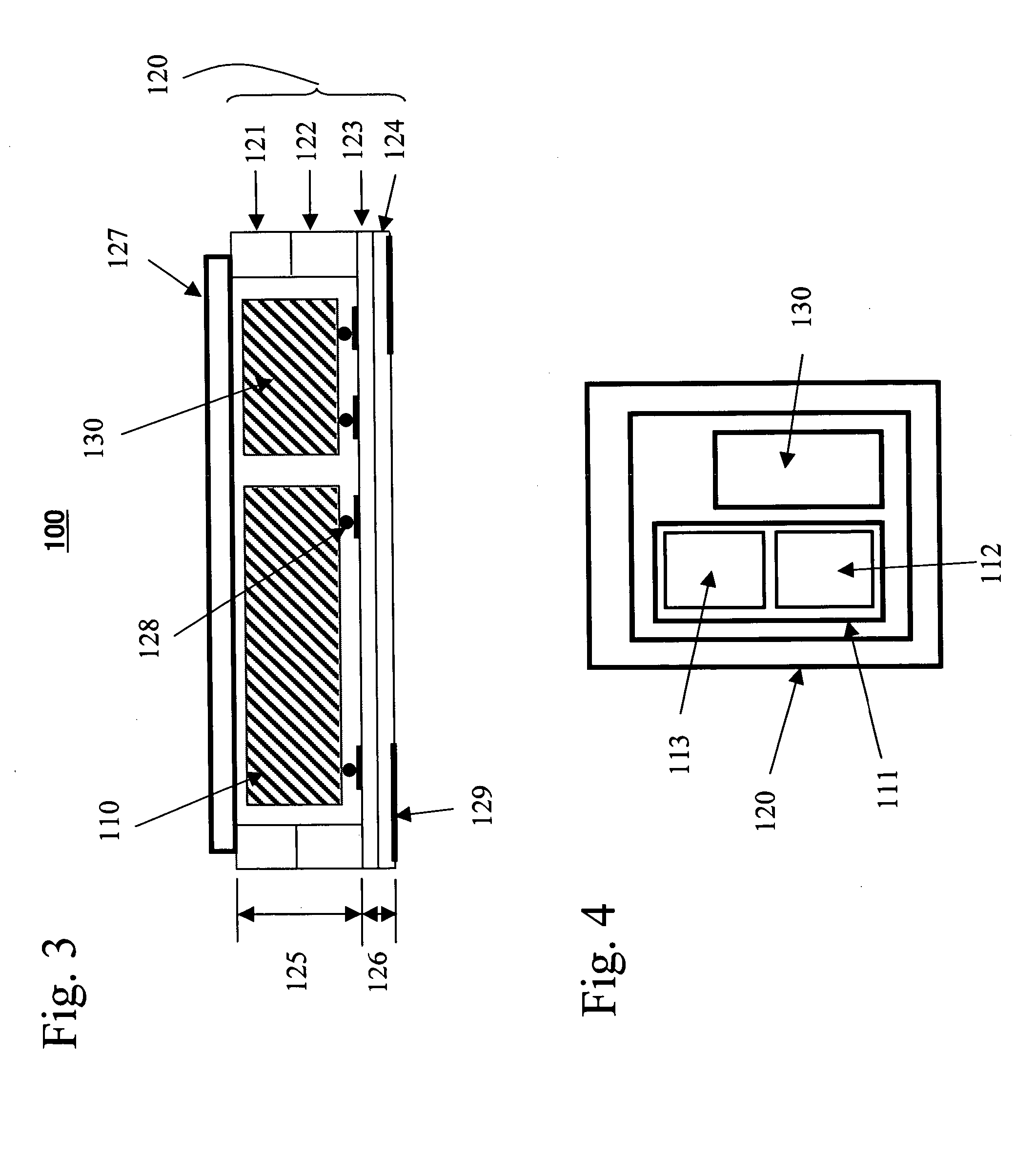
[0040]FIG. 3 is a cross-sectional view of a duplexer in accordance with a first embodiment of the present invention. The duplexer 100 includes a filter chip 110, a phase matching circuit 130, and a laminated package 120. The duplexer 100 embodies the circuit structure illustrated in FIG. 1. The laminated package 120 has ceramics layers 121 through 124 stacked on one another. The layers 121 through 124 include a cap mounting layer 121, a cavity 122, a die-attach layer 123, and a line pattern / foot pad layer 124. The cap mounting layer 121 and the cavity layer 122 constitute a cavity forming layer 125 for forming a cavity in the laminated package 120. The die-attach layer 123 and the line pattern / foot pad layer 124 constitute a base layer 126 of the laminated package 120. The filter chip 110 and the phase matching circuit 130 in the cavity are face-down bonded to the die-attach face of the die-attach layer 123 with bumps 128. A circuit pattern that will be described later is also forme...

second embodiment

[0058]FIGS. 18A and 18B show a duplexer in accordance with a second embodiment of the present invention. In this embodiment, the direction of the ground current flowing through the transmission ground line pattern 151 is substantially opposite to the direction of the ground current flowing through the reception ground line pattern 152, as shown in FIG. 18A. Accordingly, the mutual inductance between the grounds can be reduced. FIG. 18B shows the filter characteristics of the second embodiment (indicated by the solid line), and the filter characteristics of a comparative example (indicated by the broken line). The comparative example has a structure in which the direction of the ground current flowing through the transmission ground line pattern 151 is substantially the same as the direction of the ground current flowing through the reception ground line pattern 152. As shown in FIG. 18B, the duplexer in accordance with the second embodiment has a higher degree of stop-band suppressi...


PUM


Abstract

A duplexer includes: a transmission filter and a reception filter that have different band center frequencies from each other; a phase matching circuit that performs phase matching on the transmission filter and the reception filter; and a laminated package that includes a first layer on which the transmission filter, the reception filter, and the phase matching circuit are mounted. In this duplexer, the first layer includes a first ground line pattern that is connected to a ground of the transmission filter, a second ground line pattern that is connected to a ground of the reception filter, a third ground line pattern that is connected to a ground of the phase matching circuit, and signal line patterns. The laminated package also includes a second layer that is located below the first layer. The second layer includes a partition ground line pattern that is located between the signal line patterns, a signal foot pad for external connection, and a ground foot pad. The first ground line pattern and the second ground line pattern are connected to the partition ground line pattern via the ground foot pad.

Description

BACKGROUND OF THE INVENTION [0001] 1. Field of the invention [0002] The present invention generally relates to duplexers, and more particularly, to a duplexer that employs an acoustic wave device such as a surface acoustic wave device or a piezoelectric thin-film device. [0003] 2. Description of the Related Art [0004] In recent years, as the mobile communication systems have developed, mobile phone handsets and mobile information terminals have rapidly spread, and the manufacturers are still competing against each other for smaller terminals with higher performance. Also, there are both analog and digital systems for mobile telephone communication, and the frequencies used in the motile communication systems range from the 800 MHz to 1 GHz band to the 1.5 GHz to 2.0 GHz. Antenna duplexer devices that employ surface acoustic wave filters have been suggested as the devices for the mobile communication. [0005] In the recent development of mobile phone handsets, the functions of the ter...

Claims


Application Information

Patent Timeline
IPC IPC(8): H03H9/70
CPCH03H9/0571H03H9/0576H03H9/14597H03H9/564H03H9/6456H03H9/706H03H9/72H03H9/725H03H9/54
Inventor IWAMOTO, YASUHIDEINOUE, SHOGOUEDA, MASANORI
Owner TAIYO YUDEN KK
Why Eureka
Try Eureka