Electronic camera

a technology of electronic cameras and cameras, applied in the field of electronic cameras, can solve the problems of low image quality, low image quality, and large weight of the shooting lens b>92/b>, and achieve the effects of reducing the worst value of release time lag, and obtaining image data reliably

Inactive Publication Date: 2006-06-22
NIKON CORP
View PDF18 Cites 39 Cited by
  • Summary
  • Abstract
  • Description
  • Claims
  • Application Information

AI Technical Summary

Benefits of technology

[0021] The present invention, in order to solve the aforementioned problems, has a purpose of providing an electronic camera which can reliably obtain image data in a good shooting condition, an electronic camera which can achieve minimum electric power consumption, an electronic camera which can decrease the worst value of release time lag by approximately one half, an electronic camera with a simplified structure, and an electronic camera which can decrease the memory capacity of the temporary storing means (later mentioned) or can increase the number of the samplings of image data.
[0022] Moreover, another purpose of the invention is to provide an electronic camera which can omit the temporary storing means (later mentioned), an electronic camera which can obtain good image data with little hand shaking, an electronic camera which can obtain good image data which has little object shifting or misfocus, an electronic camera which can effectively perform analysis of a spatial frequency component, and an electronic camera which can obtain good image data with little release time lag.

Problems solved by technology

Generally, when performing hand-held camera shooting, hand shaking often occurs.
Therefore, the image does not give a good impression.
Therefore, there is a problem in that the shooting lens 92 becomes large and heavy.
Moreover, the space to arrange the blur correction optical system 93 has to be kept in the shooting lens 92, and there is a problem in that the flexibility of design of the shooting lens 92 decreases.
Therefore, flaring easily occurs when performing back-lit shooting or the like.
Moreover, since electric power is consumed when driving the blur correction optical system 93, there is a problem in that the battery life becomes shorter.
Furthermore, there is a problem in that a small amount of noise occurs when driving the blur correction optical system 93.
On the other hand, a blurred image can occur due not only to the aforementioned hand shaking, but also due to object shifting and misfocusing.
However, since the conventional hand shaking correction mechanism only diminishes the vibration of the camera, there is a problem in that the mechanism cannot prevent object shifting and misfocusing at all.
In particular, along with the trend toward higher resolution and miniaturization of imaging elements in recent years, the light receiving area per one pixel is more and more reduced, and the effective sensitivity of the imaging element has become low.
Because of this, there is a tendency that the exposure time of the shooting element generally increases, and the chances of occurrence of hand shaking and object shifting become even higher.
Moreover, it was very difficult to accurately prevent misfocus accurately with conventional AF (automatic focus) shooting for an object which shows unpredictable movements, such as a flower which is swaying in the wind.

Method used


Image

  • Electronic camera
  • Electronic camera
  • Electronic camera

Examples


embodiments

[0081] Hereafter, the embodiments of the present invention are explained based on the drawings.

first embodiment

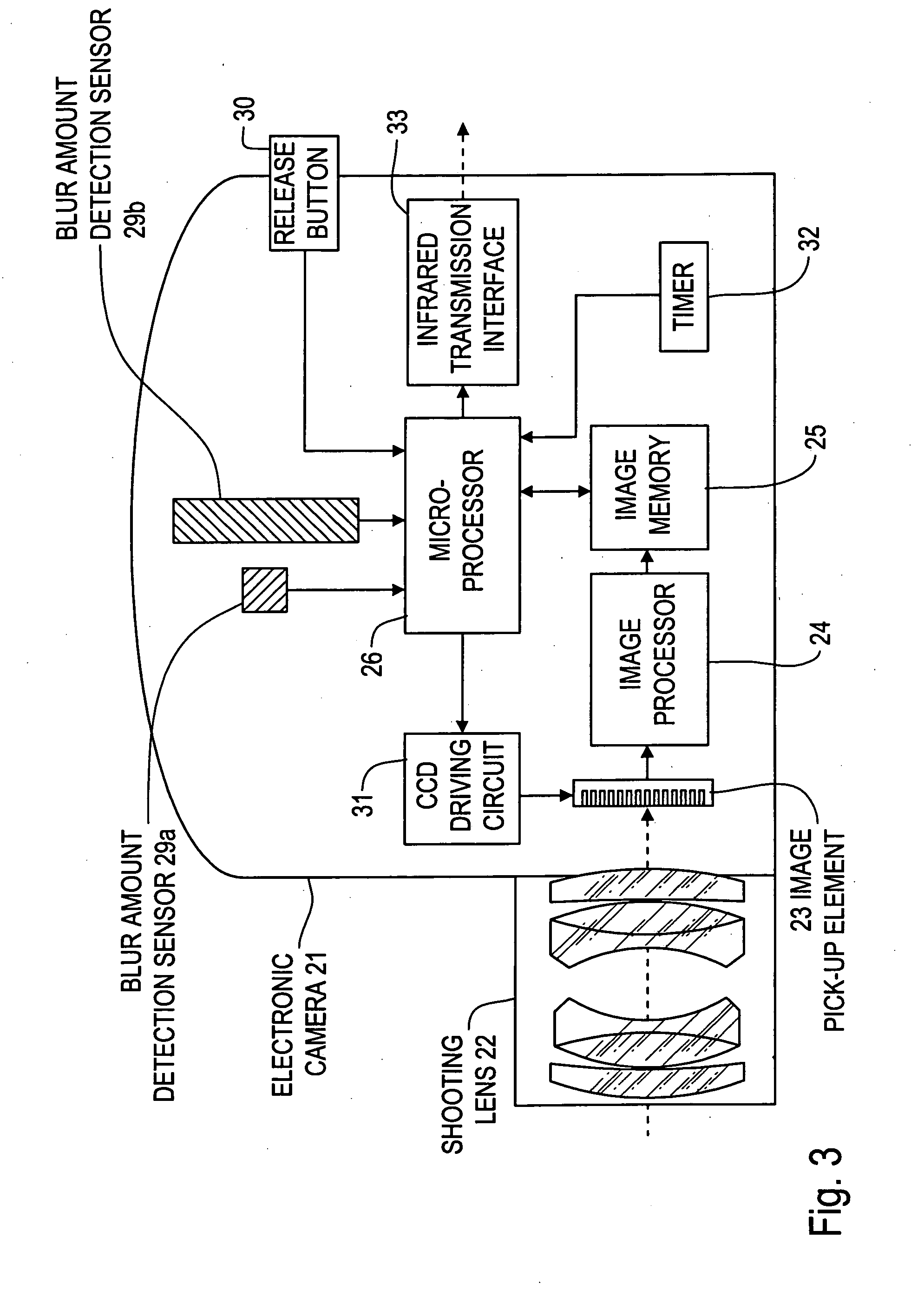
[0082]FIG. 3 is a block diagram which shows the first embodiment. Moreover, the first embodiment corresponds to the invention of claims 1, 2, 4, 5 and 7.

[0083] In FIG. 3, a shooting lens 22 is provided at the front face of the electronic camera 21. The light receiving face of an image pick-up element 23 is arranged on the image space side of the shooting lens 22.

[0084] The image output of this image pick-up element 23 is directly stored in the image memory 25 via an image processor 24 which performs color signal processing, A / D conversion, γ correction, image compression and the like. Other than this, in the image memory 25, reading and writing of the data are performed via the data bus of the microprocessor 26.

[0085] Moreover, blur amount detecting sensors 29a and 29b that are made of an angular speed sensor such as a piezoelectric gyro are arranged within the case of the electronic camera 21. The blur amount detecting sensor 29a detects the blur amount in the vertical direction...

second embodiment

[0109]FIG. 6 is a block diagram which shows the second embodiment. Moreover, the second embodiment corresponds to the invention that is described in claims 1, 3, 7 and 10.

[0110] In FIG. 6, a shooting lens 42 is provided on a front face of the electronic camera 41. The light receiving face of an image pick-up element 43 is arranged on the image space side of the shooting lens 42.

[0111] The image output from the image pick-up element 43 is connected to the data input of the image memory 45 via the image processor 44 which performs color signal processing, A / D conversion, γ correction and the like. Meanwhile, the data output of the image memory 45 is connected to the data input of the microprocessor 46.

[0112] A memory card 48 is detachably connected to the data output terminal of the microprocessor 46 via the image recording part 47.

[0113] Meanwhile, blur amount detecting sensors 49a and 49b that are composed of an angular speed sensor such as a piezoelectric gyro are arranged with...


PUM


Abstract

The present invention relates to an electronic camera which images an object image and records image data. Particularly, the present invention relates to technology to record image data in a good shooting state, such as with little blurring due to hand shaking. The invention has an image pick-up means 1 which continuously images an object, a temporary memory means 2 which temporarily stores a plurality of frames of image data which are continuously imaged by the image pick-up means 1, a shooting evaluation means 3 which evaluates a good or bad shooting state of the image data imaged by the image pick-up means 1, a still image selection means 4 which selects the image data with the highest evaluation of the shooting evaluation means 3 among the image data which are stored in the temporary memory means 2, and an image saving means 5 which saves the image data which is selected by the still image selection means 4.

Description

[0001] This is a Division of application Ser. No. 09 / 149,001 filed Sep. 8, 1998. The entire disclosure of the prior application is hereby incorporated by reference herein in its entirety.BACKGROUND OF THE INVENTION [0002] 1. Field of the Invention [0003] The present invention relates to an electronic camera which photographs an object and records image data. In particular, the present invention relates to a technology for recording image data in a good shooting condition without hand shaking or the like. [0004] 2. Description of the Related Art [0005] Generally, when performing hand-held camera shooting, hand shaking often occurs. When this kind of hand shaking occurs, since an object field is exposed in a blurry condition, an entirely blurry image is shot. [0006] In a blurry image like this, the details of the entire image and the edge portions, which should be shot clearly, are lost. Therefore, the image does not give a good impression. [0007] A conventional camera with a hand sha...

Claims


Application Information

Patent Timeline
Patent Type & Authority Applications(United States)
IPC IPC(8): H04N5/76H04N5/232
CPCH04N5/23248H04N5/23254H04N5/23258H04N5/23267H04N23/6811H04N23/683H04N23/68H04N23/6812
Inventor NOZAKI, HIROTAKEEJIMA, SATOSHI
Owner NIKON CORP
Why Eureka
Try Eureka