Capacitive pressure sensor

Inactive Publication Date: 2006-06-22
ALPS ALPINE CO LTD
View PDF5 Cites 5 Cited by
  • Summary
  • Abstract
  • Description
  • Claims
  • Application Information

AI Technical Summary

Benefits of technology

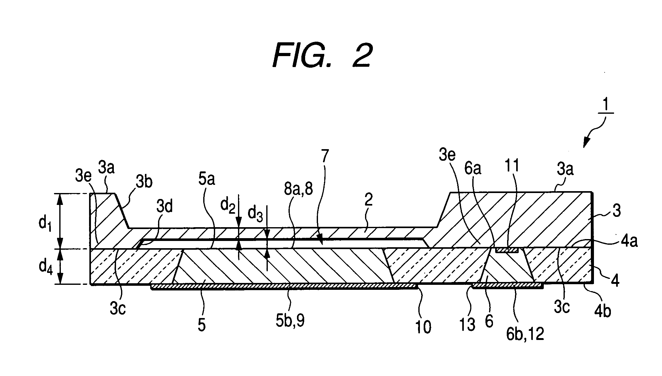
[0017] In the capacitive pressure sensor having the configuration described above, since the portion of the conductive silicon member is exposed toward the surface of the insulating substrate facing the sealed chamber so as to form the fixed electrode and another portion of the conductive silicon member is exposed toward the other surface of the insulating substrate not facing the sealed chamber so as to form the lead electrode, it is possible to form the fixed electrode, the lead wiring lines thereof, and the first lead electrode by using the conductive silicon member. As a result, the configuration of the capacitive pressure sensor can be simplified. Further, since it is not necessary to provide the space for forming the lead wiring lines in the vicinity of the sealed chamber, it is possible to make the capacitive pressure sensor small and to eliminate the parasitic capacitance. Furthermore, since it is not necessary to provide a separate structure for reducing the parasitic capacitance, the capacitive pressure sensor can be made thin.
[0018] Further, in the capacitive pressure sensor, since the conductive silicon member is buried to pass through between the surface of the insulating substrate facing the sealed chamber and the other surface of the insulating substrate not facing the sealed chamber, the lead electrode becomes located on the other surface of

Problems solved by technology

As a result, there is a possibility that the parasitic capacitance will cause the pressure sensitivity of the capacitive pressure sensor to be lowered.
Accordingly, there has been a problem in that the pressure sensor cannot be made small.
For this reason, there has been a problem in that it is difficult to make the pressure sensor thin.
Further, in order to prepare the lead wiring lines, complicated processes are needed in which the first opening portion is prov

Method used


Image

  • Capacitive pressure sensor
  • Capacitive pressure sensor
  • Capacitive pressure sensor

Examples


Embodiment Construction

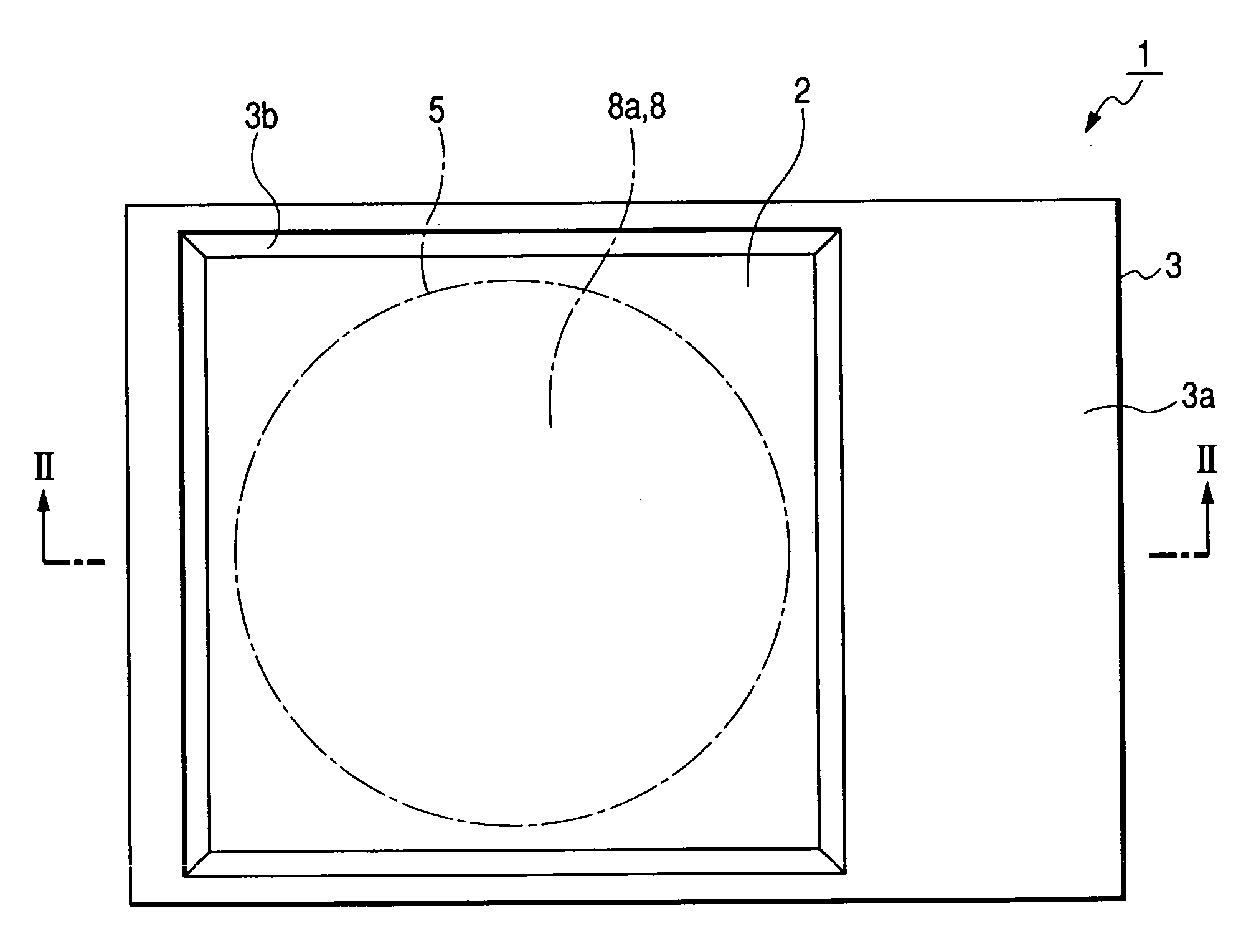
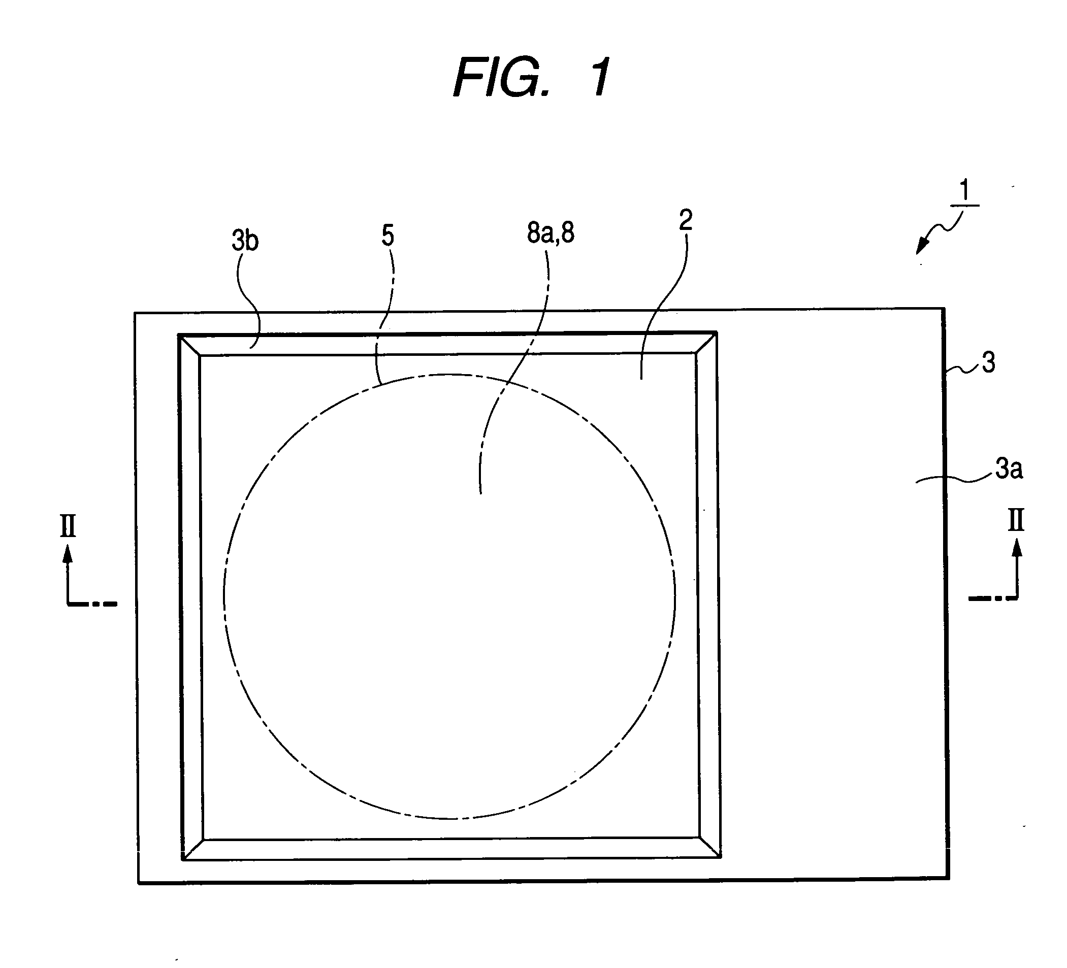
[0028] Hereinafter, the preferred embodiments of the invention will be described with reference to the accompanying drawings. FIG. 1 is a plan view illustrating an example of a capacitive pressure sensor according to the present embodiment, and FIG. 2 is a cross-sectional view taken along the line II-II of FIG. 1. FIGS. 3A to 3C and 4A to 4C are process views explaining a method of manufacturing a capacitive pressure sensor. FIGS. 5A to 5C are cross-sectional views explaining another example of the capacitive pressure sensor according to the present embodiment and a method of manufacturing the same. FIG. 6 is a cross-sectional view illustrating another example of the capacitive pressure sensor according to the present embodiment.

[0029] Further, FIGS. 1 to 6 are views explaining the configuration of the capacitive pressure sensor according to the present embodiment and the method of manufacturing the same, the measuring range of the capacitive pressure sensor being 0 to several hund...


PUM


Abstract

A capacitive pressure sensor includes: a conductive silicon substrate having a diaphragm; an insulating substrate having a fixed electrode, the insulating substrate overlapping the conductive silicon substrate so as to be bonded thereto; and a sealed chamber formed between the diaphragm and the fixed electrode. A conductive silicon member is buried in a part of the insulating substrate, a portion of the conductive silicon member is exposed toward a surface of the insulating substrate facing the sealed chamber so as to form the fixed electrode, and another portion of the conductive silicon member is exposed toward the other surface of the insulating substrate not facing the sealed chamber so as to form a lead electrode of the fixed electrode.

Description

BACKGROUND OF THE INVENTION [0001] 1. Field of the Invention [0002] The present invention relates to a capacitive pressure sensor having a diaphragm. [0003] 2. Description of the Related Art [0004] In recent years, a capacitive pressure sensor has been widely used in that it is small and a structure thereof is simple. For example, the capacitive pressure sensor has been adopted as a means for monitoring the tire pressure of an automobile. [0005] A conventional capacitive pressure sensor is disclosed in Japanese Patent No. 2772111. As shown in FIG. 1 of Japanese Patent No. 2772111, the capacitive pressure sensor is configured such that a glass substrate is bonded to a silicon substrate having a pressure sensitive diaphragm portion, a reference pressure chamber is provided between the silicon substrate and the glass substrate in the vicinity of a location where the pressure sensitive diaphragm portion is formed, and a first electrode is formed at a side of the reference pressure chamb...

Claims


Application Information

Patent Timeline
IPC IPC(8): H01G7/00
CPCG01L9/0073
Inventor SUTO, TOSHIHIDESAKAI, SHIGEFUMITAKAHASHI, SASAHIRO
Owner ALPS ALPINE CO LTD
Why Eureka
Try Eureka