Wheel bearing assembly mount with force attenuation

a technology of force attenuation and bearing assembly, which is applied in the direction of mechanical equipment, rigid support of bearing units, transportation and packaging, etc., can solve the problems of increasing the mass, weight and cost of bearing components, increasing the weight of bearing components, and increasing the risk of damage to the bearing assembly of the vehicle. , to achieve the effect of reducing the stress concentration, and reducing the contact area

Active Publication Date: 2006-06-22
SKF USA INC
View PDF15 Cites 13 Cited by
  • Summary
  • Abstract
  • Description
  • Claims
  • Application Information

AI Technical Summary

Benefits of technology

[0005] The present invention provides a support member for a wheel bearing assembly. The support member has a central sleeve for securing bearing members therein, and a mounting flange extending from the central sleeve for securing the bearing assembly to a portion of a vehicle. The flange has a concave central portion coupled to the sleeve. The flange tapers down from the central portion into three, substantially equally angularly spaced-apart lobes projecting outwardly from the central portion. The junction between the central sleeve and the central portion of the flange has a radius formed therealong to help relieve any stress concentrations at the junction during flexing of the flange. One or more substantially flat, coplanar bearing surfaces are also formed along each of the lobes. The bearing surfaces abut the vehicle and are designed to rest flush against the vehicle when the support member is secured to the vehicle, providing a relatively limited contact area between the mounting flange and the vehicle. A chamfer may be formed at an end portion of each of the lobes to further reduce the contact area between the flange and the vehicle. Due to the generally concave shape of the portion of the mounting flange residing radially inwardly of the bearing surfaces, the central portion of the flange is spaced apart from the vehicle, and the bearing surfaces are the only portions of the flange in contact with the vehicle when the support member is secured to the vehicle. This substantially reduces the contact area between the mounting flange and the vehicle, thereby reducing and localizing any impact forces transferred to the bearing members. In addition, the central portion of the flange may be configured to act as a spring member. This enables the flange central portion to flex in response to a side impact load experienced by a wheel assembly attached to the vehicle via the wheel bearing assembly. This flexibility enables the flange to absorb a portion of the side impact load, thereby dampening or attenuating the portion of the load transmitted to the bearings.

Problems solved by technology

As larger diameter wheels, lower profile tires, and more rigid vehicle suspension components are employed in newer vehicle platforms, the vehicle wheel bearing assembly has become much more susceptible to damage resulting from side impact forces between the vehicle wheels and objects such as curbs.
This can lead to undesirable noise and vibration in the bearing during use.
However, this approach increases the mass, weight and cost of the bearing components and can render the bearing design inefficient in terms of vehicle straight-running and cornering capabilities.

Method used


Image

  • Wheel bearing assembly mount with force attenuation
  • Wheel bearing assembly mount with force attenuation
  • Wheel bearing assembly mount with force attenuation

Examples


Embodiment Construction

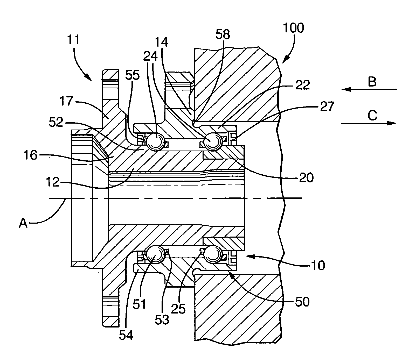
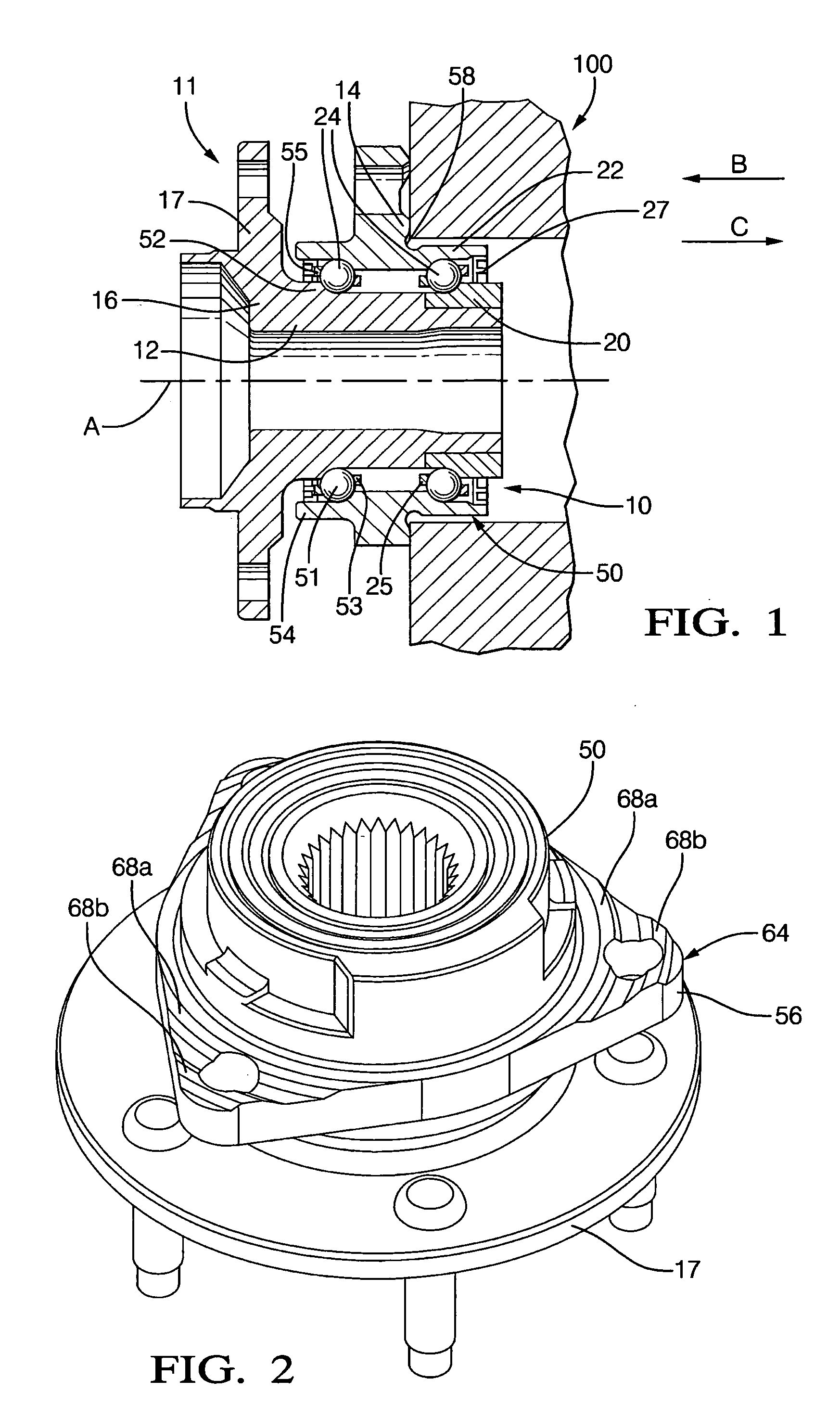
[0014] A wheel bearing assembly 10 is shown in FIG. 1 for supporting a wheel (not shown) in a wheel assembly 11. A spindle 12 defines a rotational axis A, and a support member 14 supports the spindle 12. Support member 14 may be secured to a portion 100 of the vehicle by fasteners or the like. A wheel hub 16 has a flange 17 for securing the wheel thereto and is supported on spindle 12 adjacent support member 14. In the embodiment shown in FIG. 1, wheel hub 16 is integrally formed with spindle 12. Wheel hub 16 and spindle 12 are rotatable about rotational axis A. A drive mechanism (not shown) is coupled to spindle 12 for rotationally driving the wheel. Bearing assembly 10 is arranged to permit wheel hub 16 and spindle 12 to rotate relative to support member 14, with support member 14 rotatably supporting spindle 12. For purposes of the present invention, spindle 12 is “rotatably supported” by support member 14 when the spindle is supported so as to permit rotation of the spindle.

[00...


PUM


Abstract

A support member (14) for rotatably coupling a first element to a second element. The support member includes a sleeve (50) for rotatably supporting the first element, and a flange (56) having a concave central portion. The flange (56) is coupled to the sleeve (50). The flange (56) has bearing surfaces (68a, 68b) formed thereon along which the flange (56) is mounted to the second element. In one embodiment, the first element is a spindle (12) of a vehicle wheel assembly (11) and is rotatably supported in the sleeve (50) by rollable bearing elements positioned therein. Multiple tapered lobes (64) extend outwardly from the sleeve (50), and the support member (14) is mounted to a vehicle via bearing surfaces (68a, 68b) along the lobes (64). Due to the concave portion of the flange (56), the bearing surfaces (68a, 68b) are the only portions of the flange (56) in contact with the vehicle when the support member (14) is secured to the vehicle, reducing the contact area between the flange (56) and the vehicle, and reducing impact forces transferred to the bearings. A portion of the flange (56) may act as a spring member, enabling the flange (56) to flex in response to an impact load experienced by the wheel bearing assembly (11). This enables the flange (56) to absorb a portion of the side impact load, thereby attenuating the portion of the load transmitted to the bearings. A wheel bearing assembly (10) incorporating the support member (14) is also disclosed.

Description

CROSS REFERENCE TO RELATED APPLICATIONS [0001] This application claims the benefit of provisional application Ser. No. 60 / 637,546, filed on Dec. 20, 2004.BACKGROUND OF THE INVENTION [0002] This invention relates to wheel bearing assemblies for supporting a wheel and, more particularly, to an apparatus and method for attenuating impact forces transmitted to ball bearings in a wheel bearing assembly. [0003] A wheel bearing assembly is used between a spindle and either a support member or a wheel hub (depending on the particular assembly configuration) for permitting relative rotation between the spindle and the support member or wheel hub. As larger diameter wheels, lower profile tires, and more rigid vehicle suspension components are employed in newer vehicle platforms, the vehicle wheel bearing assembly has become much more susceptible to damage resulting from side impact forces between the vehicle wheels and objects such as curbs. These side impact forces act in a direction general...

Claims


Application Information

Patent Timeline
Patent Type & Authority Applications(United States)
IPC IPC(8): F16C13/00
CPCB60B27/00F16C19/186F16C27/04F16C35/067F16C2326/02
Inventor MEEKER, STEVEN E.MISCHLER, DAVID B.
Owner SKF USA INC
Why Eureka
Try Eureka