Image forming apparatus

a technology of forming apparatus and forming fluid, which is applied in the direction of electrographic process apparatus, instruments, optics, etc., can solve the problems of offset of toner image, inability to fix toner image, and deterioration of image, so as to reduce the consumption of fixer fluid and heat energy and electric power consumption, no wrinkles, and short time

Inactive Publication Date: 2006-06-22
SHARP KK
View PDF5 Cites 9 Cited by
  • Summary
  • Abstract
  • Description
  • Claims
  • Application Information

AI Technical Summary

Benefits of technology

[0012] An object of the invention is to provide an image forming apparatus which causes no disturbance in a toner image due to flux and agglomeration of a toner and which causes no curls, no wrinkles, etc. on a recording medium, at the time of fixing the toner image to the recording medium by use of a liquid fixer fluid, and which can reduce consumption of the fixer fluid and heat energy and electric power consumption, and can fix even a multicolored toner image for a relatively short time.

Problems solved by technology

However, this image forming apparatus has disadvantages of image deteriorations such that the toner image is not fixed and that offset of the toner image is caused, due to decrease of a temperature of the toner image when the toner image and the recording medium come into contact with each other at the time of transfer and fixation because the recording medium is not heated in this image forming apparatus.
Furthermore, heating means having a large heat capacity becomes necessary for heating the toner image and the recording medium and therefore, the electric power consumption becomes so larger as to occupy more than half of total electric power consumption in the image forming apparatus in the present circumstances.
Since the image forming apparatus of electrophotographic system is commonly used, it is required also in the image forming apparatus of electrophotographic system to reduce the electric power consumption at the time when the toner is fixed to the recording medium Further, in the thermal fixing system, an interior portion of the apparatus has a high temperature by use of the heating means inside the apparatus as described above and therefore, it is necessary to enhance heat resistance of components, so that a material cost increases.
Furthermore, in the thermal fixing system, a fixing operation cannot be performed until when a temperature of a fixing portion increases to the predetermined temperature.
Accordingly, it tends to take a long time before the fixing operation can start, which time is a warm-up time in other words.
Furthermore, the thermal fixing system has a problem that it takes a longer time for fixing a multicolored toner image to the recording image than fixing a monochromatic toner image.
However, unfixed toner image is no more than an agglomeration of toner particles without physically or chemically binding force in a room temperature.
As a result, a blur is generated on an image edge after fixation and in addition, a halftone portion which should be even, have uneven density so that an image of high quality cannot be obtained.
However, when the fixer fluid is thus applied locally to the recording medium, the image portion expands and contracts while the non-image portion does not expand or contract, and therefore it is not possible to prevent wrinkles from being generated around the image portion.
However, it is difficult to exactly measure the minimum amount because the minimum amount is extremely small.
Further, when the fixer fluid is applied to only the toner attached portion, the toner attached by fog or the like on the non-image portion around the toner attached portion remains on the recording medium without being fixed so that the toner may mess hands, clothes or the like.
However, in order to enhance adherence between the toner image and the recording medium and adherence among the toner particles in a case where heat is not supplied at the time of transfer and fixation, and no other particular measures are taken as in the case of the JP-A 10-063121, a large amount of the fixer fluid becomes necessary.
When the large amount of the fixer fluid is used, it is not possible to prevent wrinkles, curls and the like from causing on the recording medium.
In addition, it becomes necessary to replenish the fixer fluid with frequency, with the result that maintenance is deteriorated.
Alternatively, a high-capacity fixer fluid storing tank becomes necessary, with the result that the apparatus cannot be small in size.

Method used


Image

  • Image forming apparatus
  • Image forming apparatus
  • Image forming apparatus

Examples


first embodiment

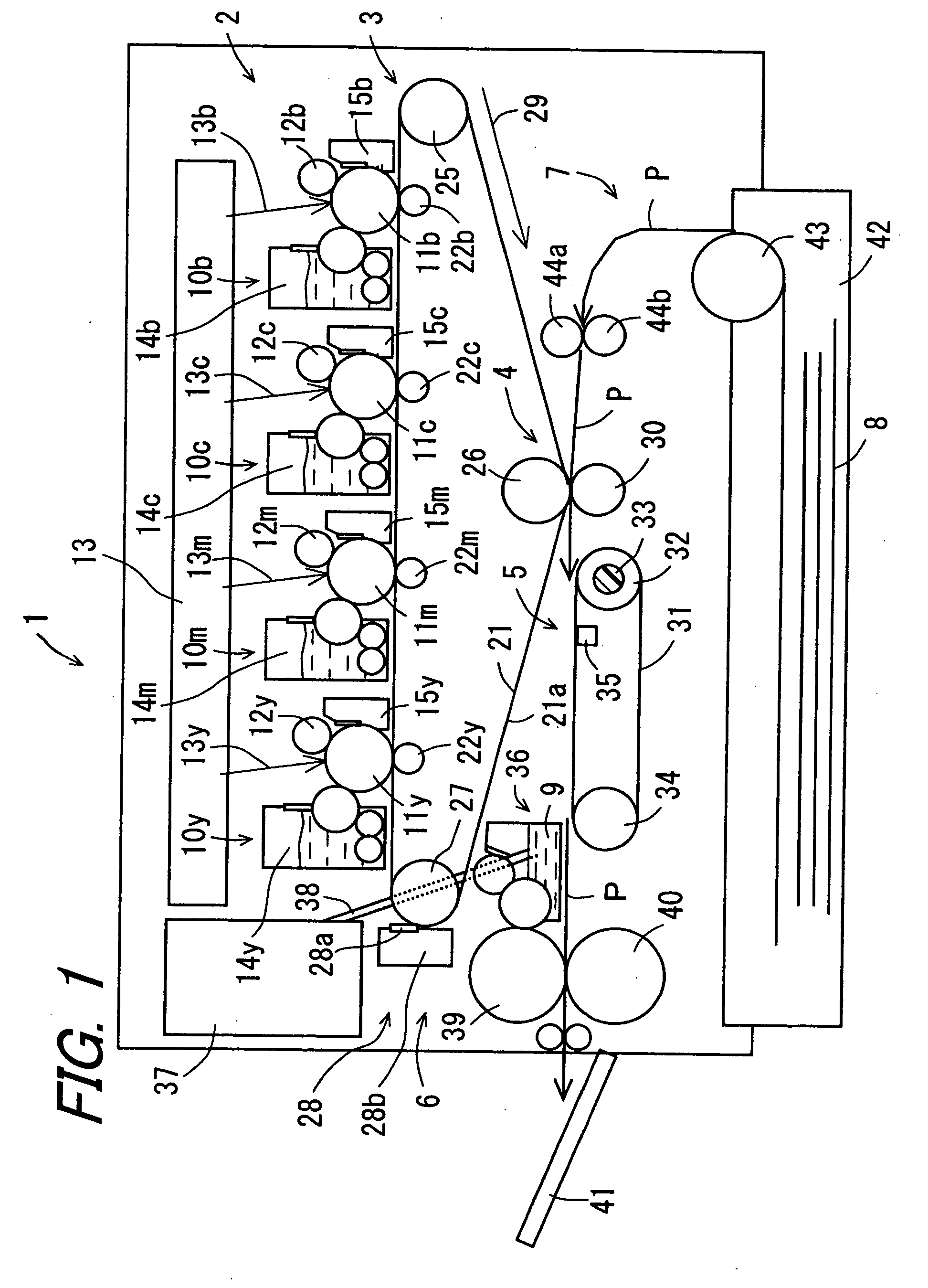
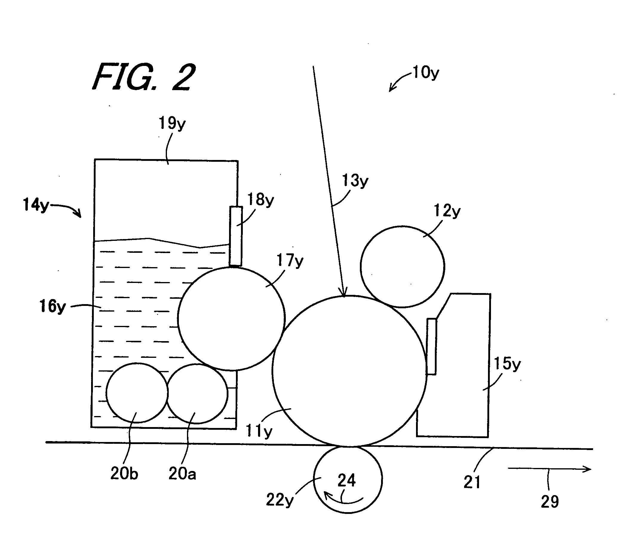
[0108]FIG. 1 is a sectional view schematically showing a configuration of an image forming apparatus 1 according to the invention. FIG. 2 is an enlarged sectional view showing a configuration of a substantial part (a toner image forming section 2 which will be described hereinbelow) of the image forming apparatus 1 shown in FIG. 1. FIG. 3 is an enlarged sectional view showing a configuration of the substantial part (a secondary transfer section 4, a heating section 5, and a fixer fluid applying section 6, which will be described hereinbelow) of the image forming apparatus shown 1 in FIG. 1. FIG. 4 is a sectional view schematically showing a configuration of a fixing roller 39.

[0109] The image forming apparatus 1 comprises a toner image forming section 2, an intermediate transfer section 3, a secondary transfer section 4, a heating section 5, a fixer fluid applying section 6, and a recording medium supplying section 7.

[0110] The toner image forming section 2 comprises image forming ...

second embodiment

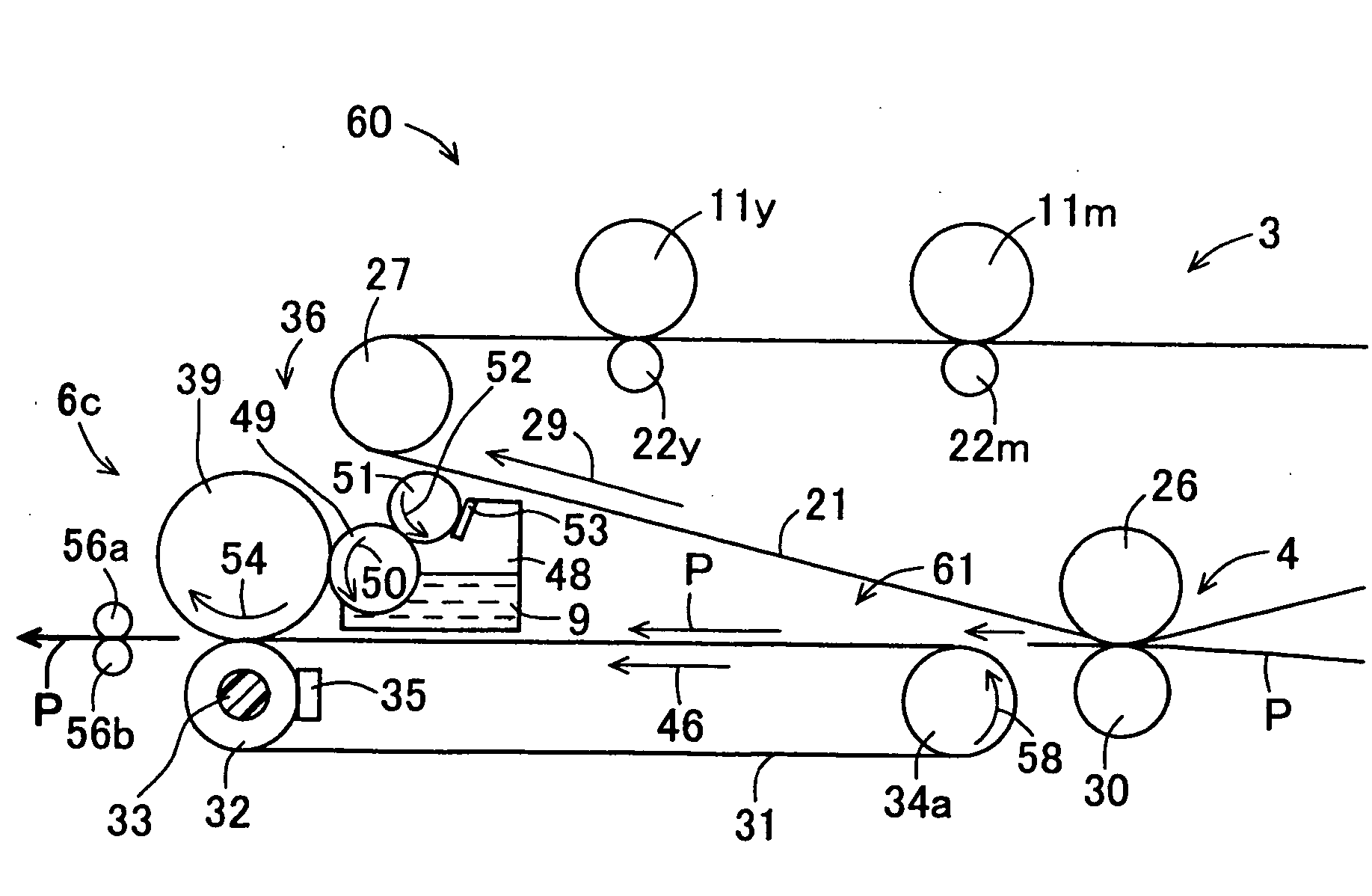
[0171]FIG. 5 is a side view schematically showing a configuration of a substantial part of an image forming apparatus 60 according to the invention. The image forming apparatus 60 is similar to the image forming apparatus 1, so that illustration and description of parts of the image forming apparatus 60, which parts have the same configuration as those of the image forming apparatus 1, will be omitted. Further, corresponding parts among the parts shown in FIG. 5 will be denoted by the same reference numerals, and description thereof will be omitted.

[0172] The image forming apparatus 60 has no pressure roller 40 which is included in the image forming apparatus 1. In a heating section 61 of the image forming apparatus 60, the heating roller 32 is used as one of the two rollers for stretching the conveying belt 31 and further, the heating roller 32 and the fixing roller 39 come into pressure-contact with each other via the conveying belt 31 so that the heating roller 32 functions as a ...

third embodiment

[0183]FIG. 6 is a side view schematically showing a configuration of a substantial part of an image forming apparatus 62 according to the invention. FIG. 7 is an enlarged side view showing the substantial part of the image forming apparatus shown 62 in FIG. 6.

[0184] The image forming apparatus 62 is similar to the image forming apparatus 1, so that corresponding parts will be denoted by the same reference numerals, and description thereof will be omitted. Further, illustration and description of the same parts will be omitted.

[0185] In the image forming apparatus 62, a heating roller 32a serving as a hating section, and a fixer fluid supplying section 6a contact an intermediate transfer belt 66 between a downstream side in a rotation direction (an arrow sign 29 direction) of the intermediate transfer belt 66 to the intermediate transfer position of the toner image from the photoreceptor drums 11y, 11m, 11c and 11b onto the intermediate transfer belt 66, and an upstream side in the ...


PUM


Abstract

An image forming apparatus is provided in which a toner is prevented from flowing and being agglomerated, at the time of application of a fixer fluid to a toner image so as to fix the toner image to a recording medium, and the recording medium is prevented from generating curl and wrinkle, and consumption of the fixer fluid and electricity can be reduced, and even a multicolored toner image can be fixed for a relatively short time. An image forming apparatus includes a toner image forming section, an intermediate transfer section, a secondary transfer section, a heating section, a fixer fluid applying section, and a recording medium supplying section. A recording medium carrying the toner image on a surface thereof is heated by the heating section and then, a fixer fluid is applied to the toner image by the fixer fluid applying section so that the toner image is fixed.

Description

BACKGROUND OF THE INVENTION [0001]1. Field of the Invention [0002] The present invention relates to an image forming apparatus. [0003] 2. Description of the Related Art [0004] In an image forming apparatus of electrophotographic system commonly used for copying machine, printer, facsimile and the like, a photoreceptor having a photosensitive layer containing a photoconductive substance formed on a surface thereof is used. In this case, after an electric charge is given to a photoreceptor surface so as to uniformly charge therewith, an electrostatic latent image corresponding to image information is formed by various image forming processes. This electrostatic latent image is developed by a developer supplied from developing means, the developer containing a toner, so as to make a toner image. This toner image is directly transferred to a recording medium such as a paper, or once transferred to an intermediate transfer medium and then further transferred to the recording medium. And ...

Claims


Application Information

Patent Timeline
Patent Type & Authority Applications(United States)
IPC IPC(8): G03G15/16G03G15/20
CPCG03G15/2025G03G2215/2093
Inventor ASAKURA, KENJIYAMANA, SHINJIKAMEI, YUKIKAZU
Owner SHARP KK
Why Eureka
Try Eureka