Summer and winter mode operation of fuel cell stacks

a fuel cell and winter mode technology, applied in the field of summer and winter mode operation of fuel cell stacks, can solve the problem of small performance penalty associated with winter mode during normal operation, and achieve the effect of maximizing cell performance during normal operation, small performance penalty, and quick removal of water

Inactive Publication Date: 2006-06-22
BDF IP HLDG
View PDF11 Cites 27 Cited by
  • Summary
  • Abstract
  • Description
  • Claims
  • Application Information

AI Technical Summary

Benefits of technology

[0012] The difference between the modes relates to the hydration level in the fuel cell. In summer mode, the oxidant relative humidity within the cell is greater than 100% over some portion of the oxidant channel length during steady state operation. That is, at some load or loads in steady state operation, at least a portion of the cell is oversaturated. In winter mode, the relative humidity within the cell is less than 100% over essentially the entire oxidant channel length during steady state operation. That is, the cell is essentially undersaturated throughout. (The fuel cell generally comprises an oxidant reactant flow field channel with an inlet and an outlet. Herein, it is the span from the oxidant channel inlet to the channel outlet which defines this oxidant channel length.) In summer mode, since the cell is operated in an oversaturated condition, cell performance during normal operation can be maximized. In an automotive application, operating at maximum performance is particularly important on hot summer days in order to be able to reject the waste heat produced by the fuel cell through the vehicle radiator.
[0013] On the other hand, in winter mode, the cell is always operating undersaturated and is thus in a desirable state for shutdown at any time because the water content is already adequately low throughout. An advantage of winter mode operation is that the startup time from below freezing temperatures is less than it would be if operated in summer mode prior to shutdown. Another advantage of winter mode operation is that the operating conditions are suitable for quickly removing any water created within the cell during a startup from below freezing (it being typically more difficult to remove water when the stack is cold). There can be a small performance penalty associated with winter mode during normal operation. This is generally acceptable since, insofar as waste heat rejection is concerned, it is relatively easy to reject the waste heat at low ambient “winter” temperatures.
[0014] In a typical solid polymer electrolyte fuel cell, the ionic conductivity of the electrolyte (e.g., a perfluorosulfonic acid polymer) increases with hydration level and is for instance greater at 100% relative humidity than at less than 100% relative humidity. For improved performance during steady state operation in summer mode, the relative humidity within the cell is thus preferably greater than 100% over more than 50% of the oxidant channel length (that is, most of the cell is in an oversaturated condition). In winter mode, it is also preferred for performance reasons to operate at relatively higher hydration levels. Thus, during steady state operation in winter mode, the relative humidity within the cell is preferably greater than 60% over essentially the entire oxidant channel length. Typical membrane electrolytes would not be expected to have an acceptable ionic conductivity at a lower relative humidity than this. Most preferably, the relative humidity within the cell is greater than 80% over essentially the entire oxidant channel length during steady state operation in winter mode.

Problems solved by technology

There can be a small performance penalty associated with winter mode during normal operation.

Method used


Image

  • Summer and winter mode operation of fuel cell stacks
  • Summer and winter mode operation of fuel cell stacks
  • Summer and winter mode operation of fuel cell stacks

Examples


example 1

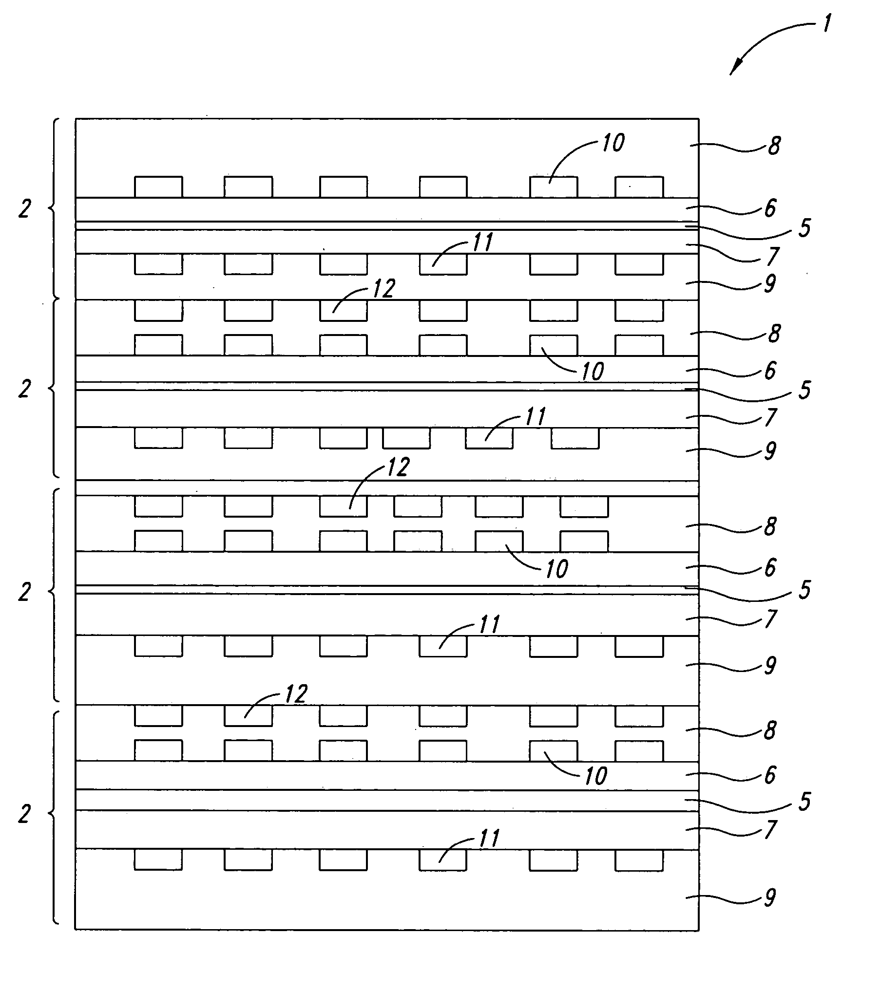
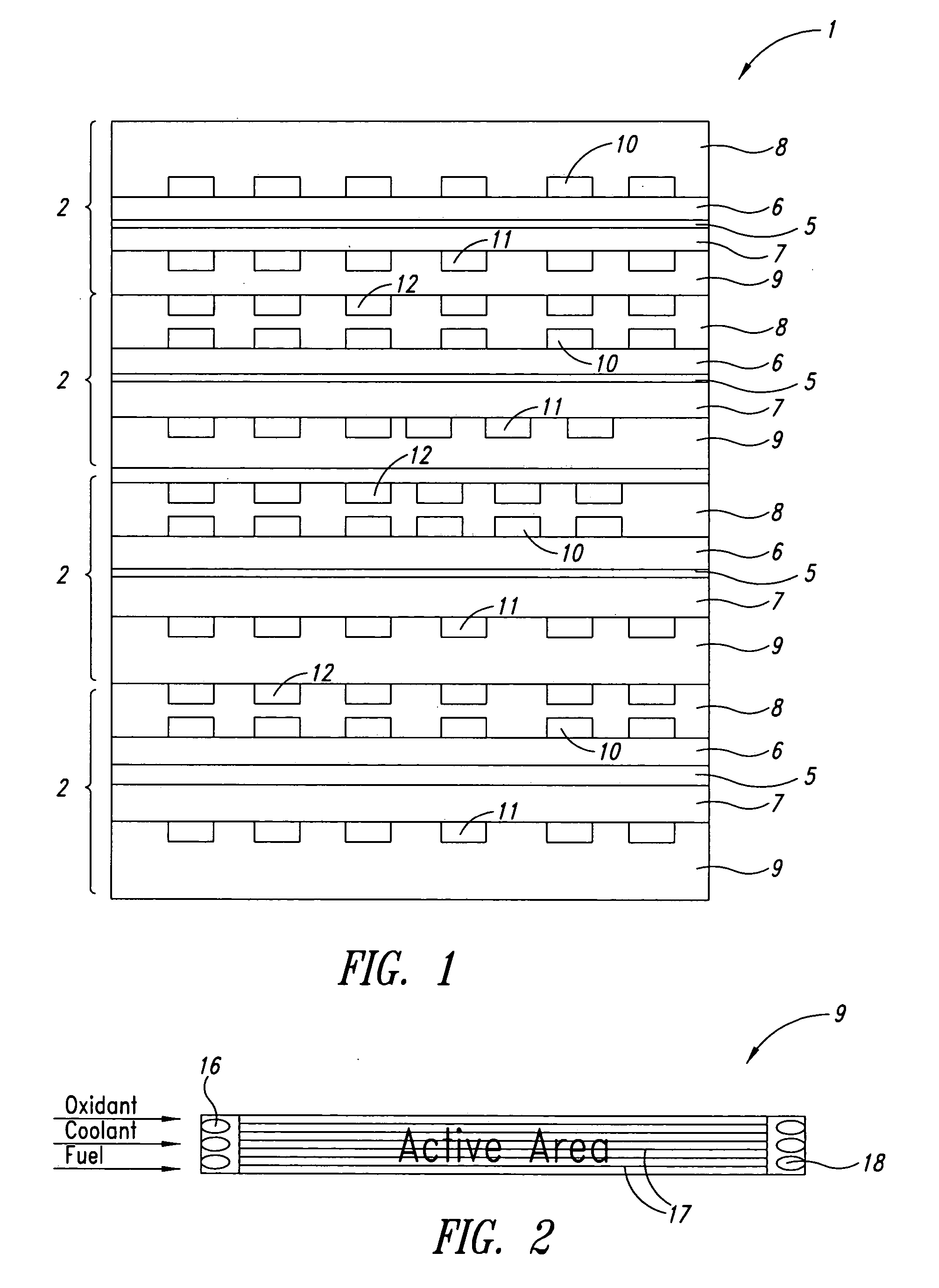
[0054] In the following, the fuel cell being considered was a solid polymer electrolyte fuel cell designed for use in an 100 kW automobile engine stack. The flow field plate design was similar to that shown in FIG. 2 in which both fuel (hydrogen) and oxidant (air) reactants as well as coolant (antifreeze solution) were distributed via a series of straight, parallel flow channels and in which both reactant flows and coolant flow were co-flow.

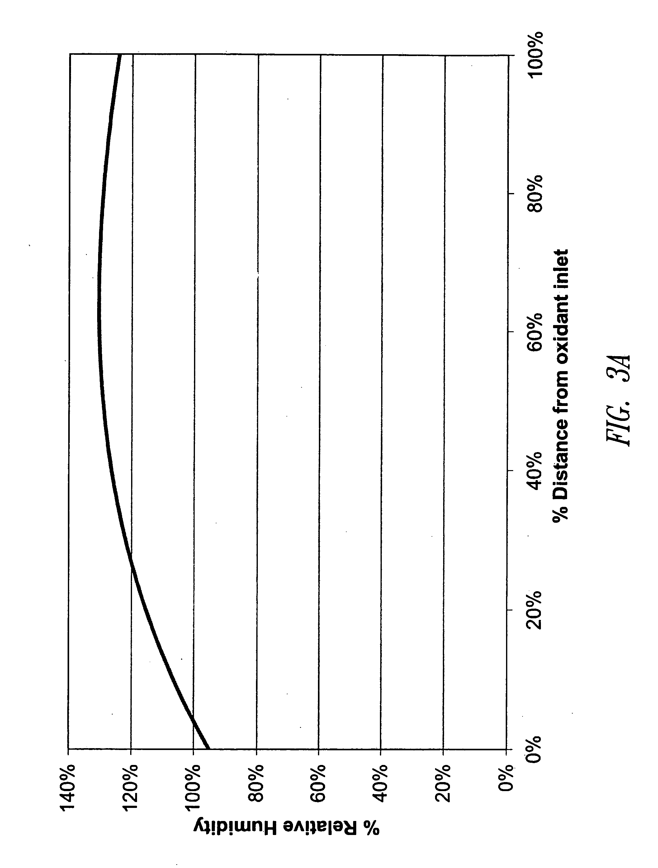
[0055] For optimum performance of this fuel cell during normal operation, the set of operating parameters shown in Table 1 was used. Note that different values were employed for different electrical loads. Table 1 lists values for three illustrative load points (maximum load of 400 A, partial load of 240 A, and a minimum idle load of 2 A). The relative humidity versus oxidant channel length profiles for this cell at these three loads were calculated using the above model and are plotted in FIGS. 3a, 3b, and 3c (for 400 A, 240 A and 2 A loads res...

example 2

[0061] In this Example, a fuel cell with a serpentine oxidant reactant flow field undergoing the same winter mode operating conditions was modelled. Again, the fuel cell being considered was a solid polymer electrolyte fuel cell designed for use in an 100 kW automobile engine stack. However, this time the oxidant flow field design was that depicted in FIG. 7. The flow of oxidant in this Figure initially is from left to right (1st leg), then right to left (2nd leg), and finally left to right again (3rd leg). Coolant flow was linear however and always left to right. Thus, the oxidant and coolant flows are co-flow in the 1 st and 3rd legs and counter flow in the 2nd leg.

[0062] The relative humidity versus length profile for this cell can also be calculated using the model above. However, the temperature gradient goes in the opposite direction for the 2nd leg as compared to the 1st and 3rd legs. The temperature versus oxidant channel length profile thus has a zigzag shape and so does t...


PUM

PropertyMeasurementUnit
output voltageaaaaaaaaaa
RHaaaaaaaaaa
pressure dropaaaaaaaaaa

Abstract

A fuel cell subject to intermittent use may be operated in two distinct modes, a “summer” or a “winter” mode, depending on whether the cell is expected to be stored at below freezing temperatures or not. At steady state in summer mode, much of the cell interior may be fully saturated with water and thus may contain liquid water. While such conditions may be most desirable for performance reasons during operation, the presence of liquid water however may be detrimental when storing at below freezing temperatures. At steady state in winter mode, the cell interior is essentially sub-saturated throughout and liquid water is not present to form ice during storage. Winter mode operation allows for improved performance during startup, especially in automotive solid polymer electrolyte fuel cell stacks.

Description

BACKGROUND OF THE INVENTION [0001] 1. Field of the Invention [0002] The invention relates to methods for obtaining improved startup performance from fuel cells following shutdown and subsequent freezing. In particular, it relates to methods for improving startup performance in solid polymer electrolyte fuel cell stacks. [0003] 2. Description of the Related Art [0004] Fuel cell systems are presently being developed for use as power supplies in a wide variety of applications. In particular, much effort is being spent on developing fuel cell engines for automotive use because fuel cells offer higher efficiencies and reduced pollution compared to internal combustion engines. [0005] Fuel cells convert fuel and oxidant reactants to generate electric power and reaction products. They generally employ an electrolyte disposed between cathode and anode electrodes. A catalyst typically induces the desired electrochemical reactions at the electrodes. The presently preferred fuel cell type for p...

Claims


Application Information

Patent Timeline
Patent Type & Authority Applications(United States)
IPC IPC(8): H01M8/04
CPCH01M8/0263H01M8/0267H01M8/04097H01M8/04119H01M8/04156H01M8/04253H01M8/04828H01M8/04835H01M8/0485H01M8/04955H01M8/04992Y02E60/50H01M8/241H01M8/2483H01M8/02H01M8/04
Inventor BACH, PETER J.LOUIE, CRAIG R.ANDREWES, CAROLINE J. E.
Owner BDF IP HLDG
Why Eureka
Try Eureka