Internal riser inspection device and methods of using same

a riser inspection and riser technology, applied in the direction of instruments, surveying, borehole/well accessories, etc., can solve the problems of time-consuming and expensive transportation, cleaning, disassembly and assembly of riser sections, drilling rigs not being able to operate, etc., and the cost of drilling rigs is very high on a daily basis

Inactive Publication Date: 2006-06-29
HYDRIL USA DISTRIBUTION LLC
View PDF41 Cites 10 Cited by
  • Summary
  • Abstract
  • Description
  • Claims
  • Application Information

AI Technical Summary

Benefits of technology

[0012] A wireline extending between the housing of a remote wireline spool is remotely positioned on the deployment platform for raising and lowering the inspection unit. A centralizer can be connected to an external surface of the housing body. The centralizer is adapted to conform to varying pipe inner diameter sizes and has an outer periphery for slidingly contacting the pipe as the inspection unit moves through the pipe. This allows the inspection unit to have a much smaller outer diameter than the inner diameter of the pipe being inspected. The centralizer also can maintain the inspection unit substantially in the center of the inner diameter of the pipe, and can maintain the longitudinal axis of the inspection unit substantially aligned with a longitudinal axis of the pipe. An umbilical cord including a data conductor can be positioned between the proximal end of the housing and a controller remotely positioned on a deployment platform. An umbilical spool can, in turn, be positioned on the deployment platform for storing and deploying the umbilical cord.

Problems solved by technology

It is time consuming and expensive to transport, clean, disassemble, inspect and reassemble the riser sections.
During this time, unless a spare drilling riser can be obtained, the drilling rig would not be able to operate.
Drilling rigs are very costly on a daily basis.
However, there are a number of problems in doing so.
The interior of the drilling riser is often not very clean, and may be coated with dried drilling mud.
Also, there is normally not much access room on the drilling rig at the ends of each riser section for staging the equipment necessary to do the inspection.
Additionally, the riser sections often do not contain flaws and thus are subjected to unnecessary stress caused by the disassembly, inspection, and reassembly of the riser sections.

Method used


Image

  • Internal riser inspection device and methods of using same
  • Internal riser inspection device and methods of using same
  • Internal riser inspection device and methods of using same

Examples


Embodiment Construction

[0030] The present invention will now be described more fully hereinafter with reference to the accompanying drawings which illustrate embodiments of the invention. This invention may, however, be embodied in many different forms and should not be construed as limited to the illustrated embodiments set forth herein. Rather, these embodiments are provided so that this disclosure will be thorough and complete, and will fully convey the scope of the invention to those skilled in the art. Like numbers refer to like elements throughout, and the prime notation, if used, indicates similar elements in alternative embodiments.

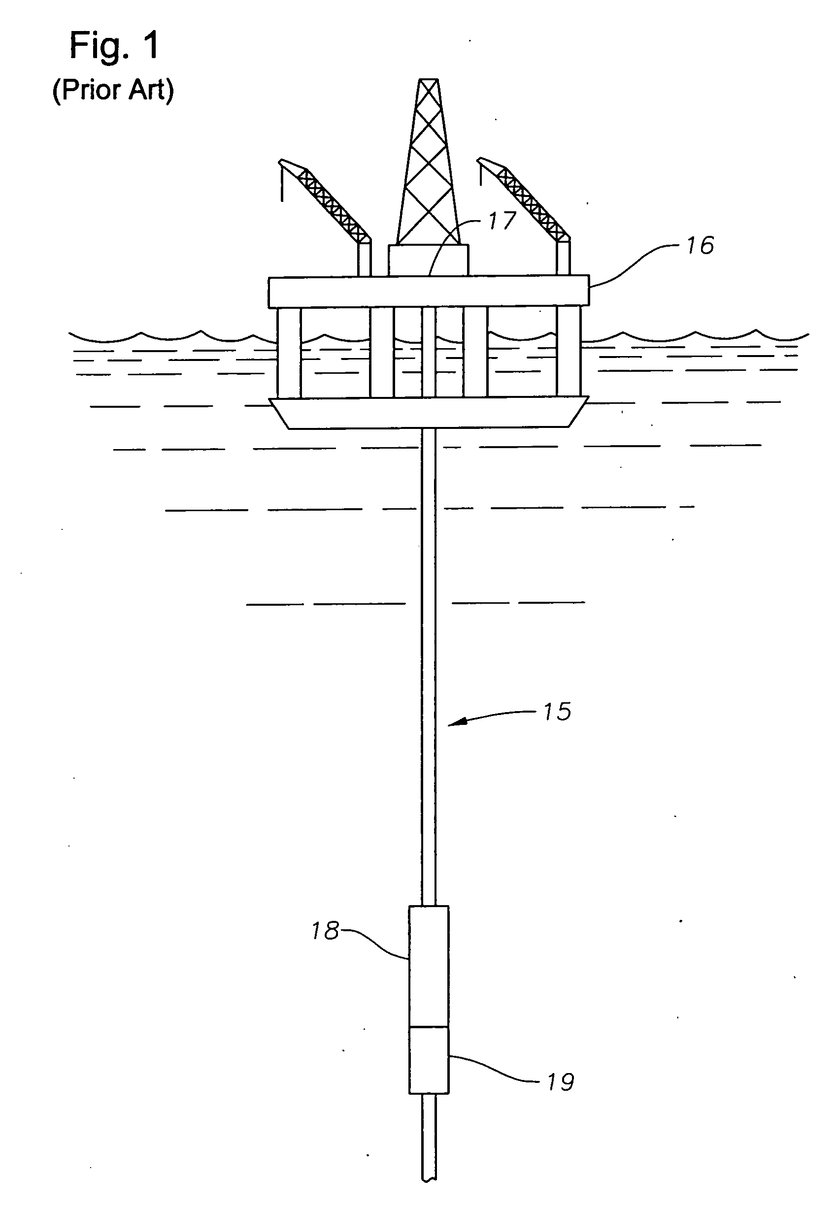
[0031] Referring to FIG. 1, shown is a deployed drilling riser pipe 15 extending between a floating vessel having an operational platform 16 and the sea bottom (not shown). A spider 17, located on the operational platform 16, provides support to a proximal end of the deployed drilling riser pipe 15. The deployed drilling riser pipe 15 is further connected at its distal...


PUM

PropertyMeasurementUnit
lengthaaaaaaaaaa
diameteraaaaaaaaaa
depthaaaaaaaaaa

Abstract

An inspection apparatus includes an inspection unit that is lowered into vertically supported pipe filled with seawater. The apparatus includes a pipe weld location detector module carried by the inspection unit. The apparatus also includes a rotating time of flight diffusion (TOFD) module and a non-rotating wall thickness module carried by the inspection unit. The module includes a pair of rotatably mounted weld volume inspection transducers rotatable by an operator and adapted to inspect for and obtain data on weld volume defects. The TOFD module has a fluid carrier positioned within the TOFD module and contains an acoustic fluid. The non-rotating wall thickness module also contains an acoustic liquid and includes a plurality of fixedly mounted wall inspection transducers adapted to obtain data on wall thickness of a portion of the pipe.

Description

RELATED APPLICATIONS [0001] This Application is a Divisional Application of Continuation-in-Part application Ser. No. 10 / 805,709, filed on Mar. 22, 2004, which claims priority to and the benefit of application Ser. No. 10 / 351,569, filed Jan. 24, 2003, now U.S. Pat. No. 6,904,818, which claims priority to and the benefit of Provisional Application Ser. No. 60 / 370,444, filed Apr. 5, 2002, each incorporated herein by reference in their entirety.BACKGROUND OF THE INVENTION [0002] 1. Field of the Invention [0003] The invention relates in general to non-destructive testing of pipe, and in particular to a test unit that is conveyed internally through pipe for ultrasonically inspecting the pipe wall thickness and welds and methods for inspecting associated therewith. [0004] 2. Description of the Related Art [0005] Non-destructive testing of pipe has been done for many years utilizing ultrasonic transducers, eddy current measurements, x-ray and other techniques. Operators using pulse echo te...

Claims


Application Information

Patent Timeline
Patent Type & Authority Applications(United States)
IPC IPC(8): E21B47/00G01B17/02G01FG01M99/00G01NG01N21/88G01N27/72G01N29/00G01N29/04G01N29/06G01N29/07G01N29/22G01N29/24G01N29/265G01N29/28G01R33/12
CPCE21B17/01E21B47/0001E21B47/0002G01B17/02G01N29/069G01N29/07G01N29/225G01N29/265G01N29/28G01N2291/015G01N2291/02854G01N2291/044G01N2291/105G01N2291/106G01N2291/2636G01N2291/2675G03B37/005G03B37/02G03B42/06E21B47/001E21B47/002
Inventor HARTHORN, LARRY K.DISHER, CHRISTOPHER B.
Owner HYDRIL USA DISTRIBUTION LLC
Why Eureka
Try Eureka