Substrate processing apparatus and method

Inactive Publication Date: 2006-06-29
DAINIPPON SCREEN MTG CO LTD
View PDF9 Cites 42 Cited by
  • Summary
  • Abstract
  • Description
  • Claims
  • Application Information

AI Technical Summary

Benefits of technology

[0017] Therefore, it is an object of the present invention to provide a technique for efficientl

Problems solved by technology

However, there is a certain limit on the efficiency of particle removal by only using the action of liquid flows.
Further, even in the case of usi

Method used


Image

  • Substrate processing apparatus and method
  • Substrate processing apparatus and method
  • Substrate processing apparatus and method

Examples


Embodiment Construction

[0029] Hereinbelow, preferred embodiments of the present invention will be described with reference to the drawings.

1. First Preferred Embodiment

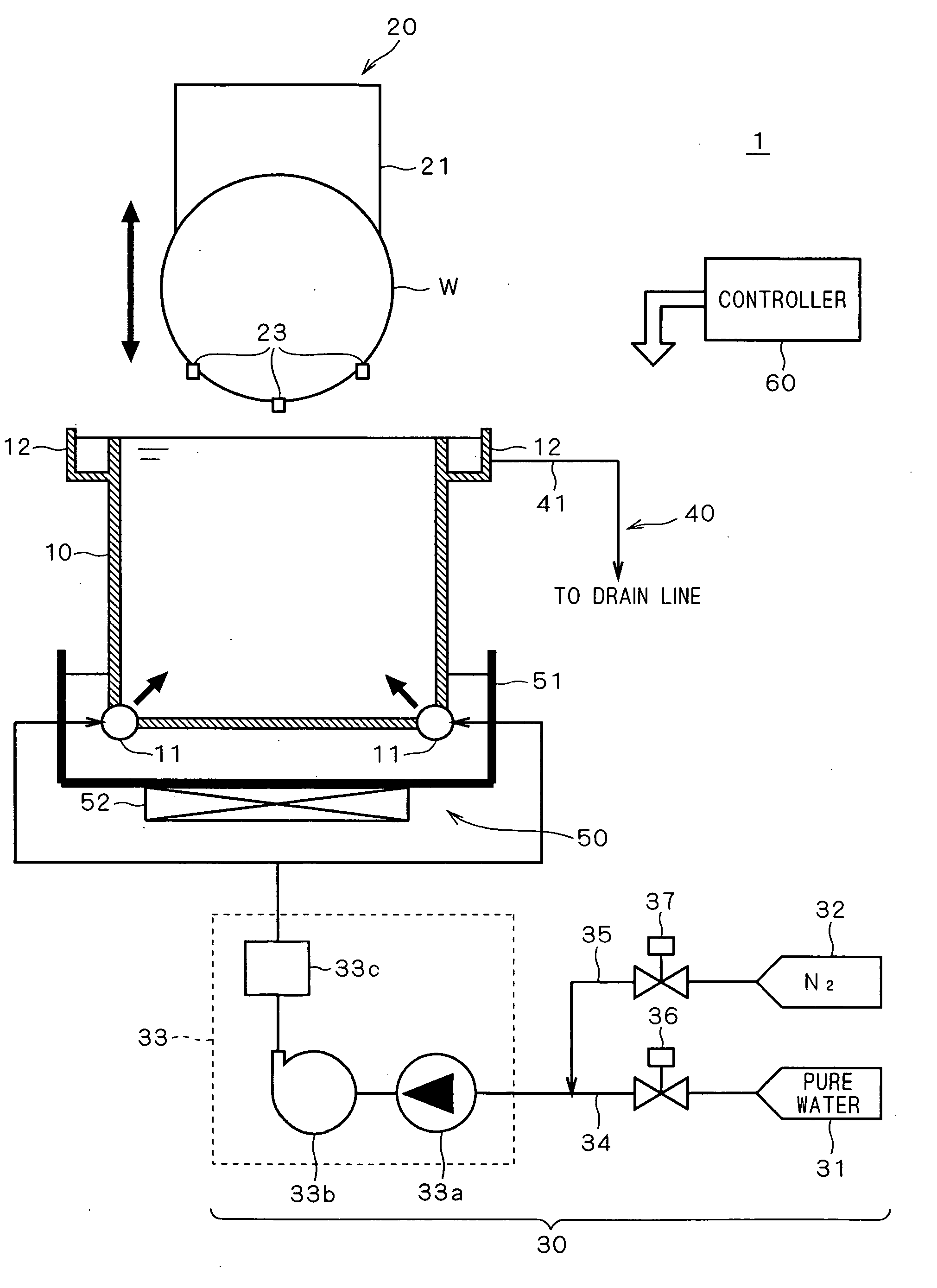
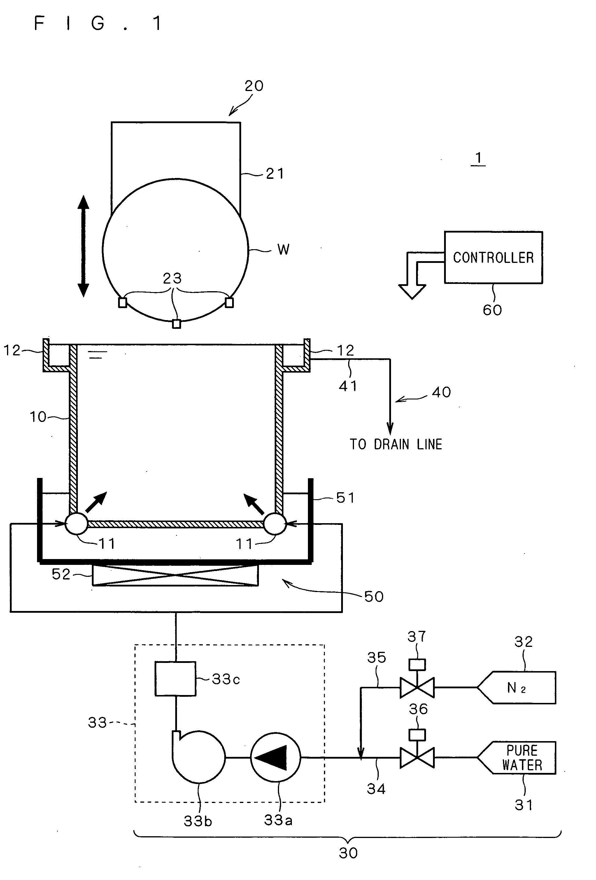
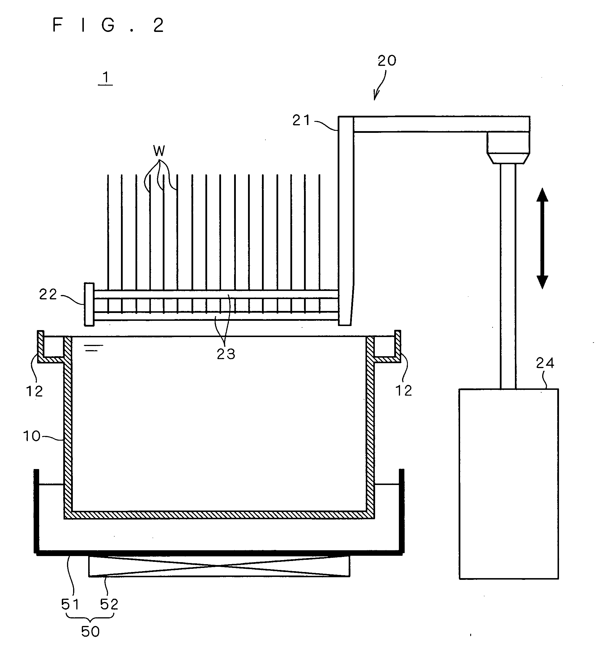
[0030] First, a first preferred embodiment of the present invention will be described. The first preferred embodiment has described the application of the present invention to a batch substrate processing apparatus. FIG. 1 is a longitudinal cross-sectional view of a substrate processing apparatus 1 taken along a plane parallel to substrates W, according to the first preferred embodiment. FIG. 1 also shows piping and the structure of a control system. FIG. 2 is a longitudinal cross-sectional view of the substrate processing apparatus 1 taken along a plane perpendicular to the substrates W.

[0031] As shown in FIGS. 1 and 2, the substrate processing apparatus 1 mainly includes a processing bath 10, a lifter 20, a pure-water supply system 30, a drainage system 40, an ultrasonic generator 50, and a controller 60.

[0032] The processing bath 10 ...


PUM


Abstract

Pure water dissolving nitrogen gas and containing microbubbles is supplied to a substrate. Since microbubbles are very minute in size and also have the electrostatic property, they can efficiently adsorb particles on the substrate surface or in the pure water. Further, since pure water dissolving nitrogen gas is unlikely to be charged, the pure water itself never carries new particles from each component of the apparatus. These functions allow efficient particle removal from the substrate surface or the liquid.

Description

BACKGROUND OF THE INVENTION [0001] 1. Field of the Invention [0002] The present invention relates to a technique for removing particles from substrate surfaces or liquids in a substrate processing apparatus for processing substrates, such as semiconductor substrates and glass substrates for liquid crystal displays or for photomasks, using liquids. [0003] 2. Description of the Background Art [0004] In the substrate manufacturing process, there are conventionally known substrate processing apparatuses for performing predetermined processing on substrates by supplying liquids such as pure water and chemical solutions to the substrates. There are mainly two types of such substrate processing apparatuses: batch substrate processing apparatuses for processing a plurality of substrates at a time which are immersed together in a liquid retained in a processing bath; and single-substrate processing apparatuses for processing a single substrate held by a holder one by one by discharging a liq...

Claims


Application Information

Patent Timeline
IPC IPC(8): B08B3/04
CPCB08B3/12B08B3/048
Inventor HASEGAWA, KOJITANAKA, MASATOHIGUCHI, AYUMIARAI, KENICHIRO
Owner DAINIPPON SCREEN MTG CO LTD
Why Eureka
Try Eureka