Friction stirring-welding method

Inactive Publication Date: 2006-06-29
HITACHI LTD
View PDF16 Cites 40 Cited by
  • Summary
  • Abstract
  • Description
  • Claims
  • Application Information

AI Technical Summary

Benefits of technology

[0011] When lapped surfaces of welding members are coated with soft metal, surface oxide films on welding boundary surfaces can be made easy to remove. In the case where welding members are made of carbon steel, such method is very effective. Nickel, zinc, and copper are especially effective as soft metal.
[0012] By providing a trapezoidal member on a surface of that member, into which a welding tool is pressed, or working the member to make the same trapezoidal in shape, it is possible to preven

Problems solved by technology

In the case where welding tools are pressed into both of an upper plate and a lower plate in lap welding by means of friction stir welding, there is caused an unfavorable problem in terms of outward appearance that a large hole is formed in a welded part to reach the lower plate.
Also, in case of lap welding of materials, such as aluminum and nickel, which are

Method used


Image

  • Friction stirring-welding method
  • Friction stirring-welding method
  • Friction stirring-welding method

Examples


first embodiment

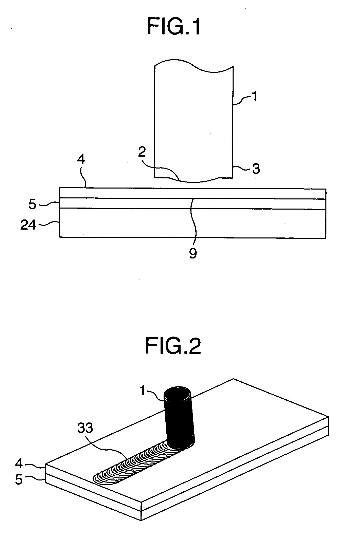
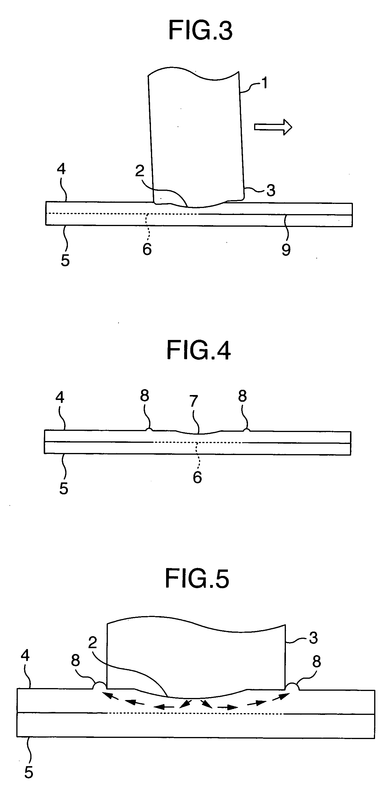
[0037]FIG. 1 is a cross sectional view showing a first embodiment. A welding tool 1 comprises a small diameter projected part 2 at the tip end of a large diameter shoulder 3. A welding test piece comprises an upper plate 4 and a lower plate 5, which lap each other and are arranged on a bearing member 24. FIG. 2 is a perspective view in the course of welding. By rotating and moving the welding tool 1 in a direction of welding in a state, in which it is pressed only into the upper plate 4 from a side of the upper plate 4, welding boundary surfaces 6 of the upper plate 4 and the lower plate 5 can be welded to each other. An indentation 7 is produced on the upper plate 4 as the welding tool 1 is moved. FIG. 3 is a cross sectional view showing a direction of welding in the course of welding. An axis of rotation of the welding tool 1 in the course of welding is inclined on an opposite side to a direction of welding indicated by an arrow, that is, a backward angle side. FIG. 4 is a cross s...

second embodiment

[0046]FIG. 11 is a cross sectional view showing a state before welding in a second embodiment. The embodiment differs from the first embodiment in that a trapezoidal member 30 is provided on a welding part of an upper plate 4 to make the upper plate 4 thick. FIG. 12 is a cross sectional view showing the welded part in the second embodiment. While an indentation 7 is produced on the welded part, any indentation does not remain and a flat surface is obtained when the welded part is ground flat.

third embodiment

[0047]FIG. 13 is a cross sectional view showing a state before welding in a third embodiment. FIG. 14 is a cross sectional view showing a welded part. The embodiment differs from the first embodiment in that a groove 32 is provided on an upper plate 4 and a projected part 31 is provided on a lower plate 5 to be fitted into the groove. Thereby, since the welding part can be made smaller in thickness than the upper plate 4, it is possible to perform welding for a further large plate thickness.


PUM

PropertyMeasurementUnit
Flow rateaaaaaaaaaa
Diameteraaaaaaaaaa
Frictionaaaaaaaaaa

Abstract

A friction stirring-welding method capable of increasing the welding strength of a lap joint. A welding tool (1) comprises a small diameter projected part (2) at the tip of a shoulder (3). The welding tool is press-fitted to the upper plate (4) of the lap joint while being rotated. By a friction stirring action, an upper plate side welding boundary surface (6) plastically flows, a surface oxidation film on a lapped surface is peeled off, and the boundary surface is activated to provide an excellent welding part. Also, since the welding tool is formed in a shape having the small diameter semispherical projected part (2) at the tip thereof, the thickness (12) of an upper plate welding part is increased, and a lap joint part with high welding strength can be provided.

Description

FIELD OF THE INVENTION [0001] The present invention relates to a friction stir welding method and a friction stir welding apparatus. DESCRIPTION OF RELATED ART [0002] A conventional technology for welding of a lap joint by means of the friction stir welding technique includes a method of using a welding tool having a flat-shaped tip end surface, or a welding tool having a recess on a tip end surface, and pressing the welding tool into one of members to cause friction stir on the one of the members to make use of plastic flow produced thereby to weld the same to the other of the members (see, for example, JP-A-2001-314981). [0003] In welding of a lap joint by means of friction stir welding, it is important to remove a surface oxide film on a lapped surface to activate a boundary interface. Therefore, it is necessary to heighten pressure of plastic flow. [0004] It is an object of the invention to provide a friction stir welding method for a lap joint, by which a welded part can be mad...

Claims


Application Information

Patent Timeline
IPC IPC(8): B23K20/12
CPCB23K20/1255B23K20/1265
Inventor AOTA, KINYAINAGAKI, MASAHISAHIRANO, SATOSHIOKAMOTO, KAZUTAKA
Owner HITACHI LTD
Why Eureka
Try Eureka