De-focus uniformity correction

a uniformity correction and uniformity technology, applied in the field of uniformity correction in lithography systems, can solve the problems of inability to realize the significant impact on the quality of devices produced by the lithography system, and inability to achieve the effect of real-time computation of three integrals over every coordinate of interes

Active Publication Date: 2006-06-29
ASML HLDG NV
View PDF2 Cites 15 Cited by
  • Summary
  • Abstract
  • Description
  • Claims
  • Application Information

AI Technical Summary

Benefits of technology

[0008] The present invention is directed to a system and method for uniformity correction by making adjustments to a correction system such that a defined uniformity specification is met while minimizing a set of selected constraints. The present invention is further directed to a method for discretizing the continuous intensity integral.

Problems solved by technology

Illumination uniformity errors can significantly impact the quality of devices produced by the lithography system.
Because of the nature of the system's operation, radiation energy in the scan direction is integrated and as a result, can be non-uniform.
Finding a comprehensive way to express the product of the transmissibility and “pupil” shape as a function of the uniformity correction mechanism adds complexity.
In addition, any algorithm that requires real-time computation of three integrals over every coordinate of interest is the illumination slot is not practical.

Method used


Image

  • De-focus uniformity correction
  • De-focus uniformity correction
  • De-focus uniformity correction

Examples


Embodiment Construction

1. Uniformity Correction System

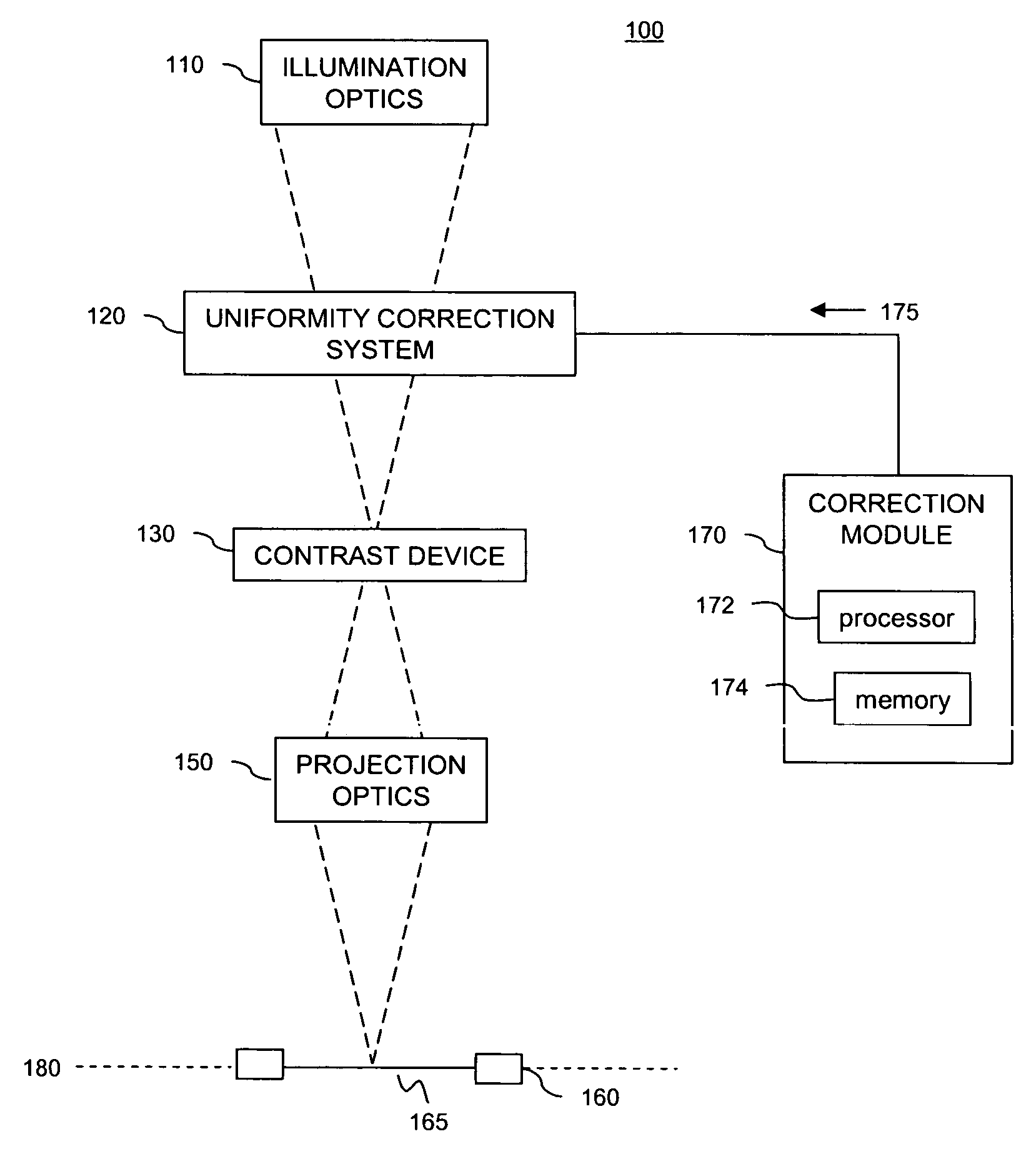
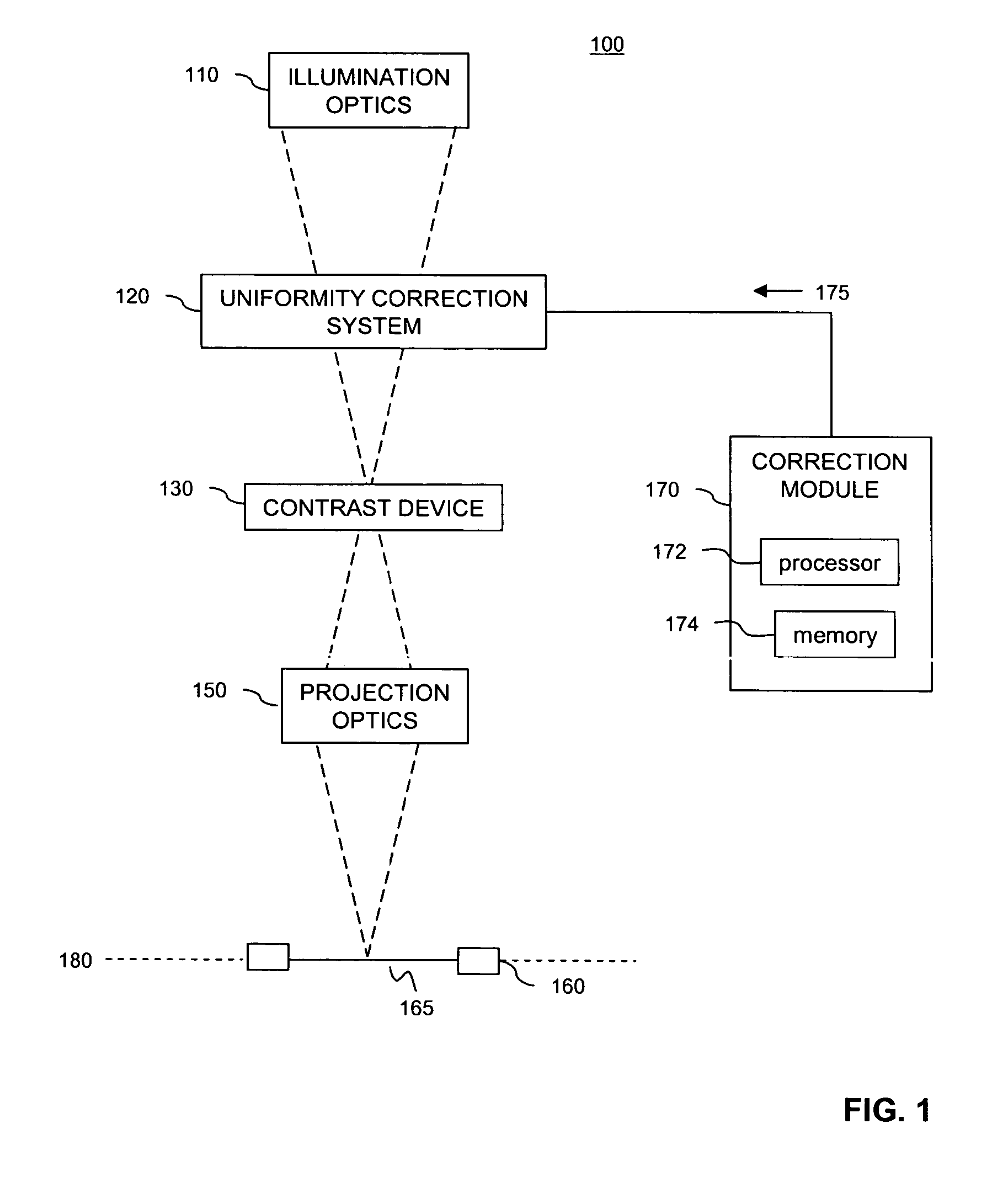
[0039]FIG. 1 is an illustration of an exemplary lithography system 100, according to an embodiment of the invention. In an embodiment, lithography system 100 is a system using a reticle or mask. In an alternate embodiment, system 100 is a maskless lighography system.

[0040] Lithography system 100 includes illumination optics 110, a uniformity correction system 120, a contrast device 130, projection optics 150, a substrate stage 160, and a correction module 170. Uniformity correction system 120 is a device that controls illumination levels within specific sections of illumination fields associated with system 100.

[0041] Uniformity correction system 120 is positioned between the illumination optics 110 and the contrast device stage 130 at the correction plane. In an embodiment, uniformity correction system 120 is located at a de-focus position. Thus, the correction system affects uniformity at the focus position. In an embodiment, the correction plane...


PUM


Abstract

A system and method for uniformity correction such that a defined uniformity specification is met while minimizing a set of selected constraints is provided. The system includes illumination optics, an opto-mechanical correction system, a contrast device, projection optics and a correction module coupled to the correction system. The correction system includes a plurality of adjustable components such as fingers. The correction module is configured to determine adjustments to the components to correct uniformity. A method for discretizing the continuous intensity integral is also provided. The illumination slot is divided into a grid having multiple grid points. “pupils” are then superimposed onto the grid. Multiple second grids are also defined. Each ““pupil”” is mapped to a second grid such that the center of the second grid is coincident with the ““pupil”” center. The continuous intensity integral is then discretized using the first grid, plurality of second grids, and ““pupil”” mappings.

Description

FIELD OF THE INVENTION [0001] The present invention is generally related to uniformity correction in lithography systems. BACKGROUND OF THE INVENTION [0002] Conventional lithography systems include, among other things, an illumination system to produce a uniform intensity distribution of a received laser beam. It is desirable that the resulting illumination be as uniform as possible and that any uniformity errors be kept as small as possible. Illumination uniformity influences the ability of an illumination system to produce uniform line widths across an entire exposure field. Illumination uniformity errors can significantly impact the quality of devices produced by the lithography system. [0003] One example of a popular conventional lithography system is a “step-and-scan” system. A “step-and-scan” system creates an illuminated slot narrower than one exposure field on the wafer. The system then scans this field along the fully exposure field and then steps to another field. This pro...

Claims


Application Information

Patent Timeline
Patent Type & Authority Applications(United States)
IPC IPC(8): G03B27/54
CPCG02B7/346G02B27/0012G03F7/70125G03F7/70191
Inventor WIENER, ROBERTO B.KREMER, ALEXANDERSTONE, ELIZABETHZIMMERMAN, RICHARD B.
Owner ASML HLDG NV
Why Eureka
Try Eureka