[0029] A still further embodiment of the invention is directed to a modular
data center having an electronic equipment rack having a front face and a back face, and a cooling unit positioned adjacent to the rack, the cooling unit having a front face and a back face, the cooling unit being configured to take in air through the back face, cool the air, and exhaust the cooled air, wherein the cooling unit is configured to release the cooled air along a substantial portion of a height of the front face of the cooling unit and direct the cooled air in a direction toward the front face of the rack. The cooling unit may include a monitoring device for monitoring at least one of a
power load to the rack, the
airflow, or a temperature of the air in the rack. The cooling unit can be configured to adjust an
airflow rate of the cooled air based on at least one of the
power load to the rack and the temperature of the air. The cooling unit may provide a substantially uniform
airflow over the substantial portion of the height of the front face of the cooling unit.
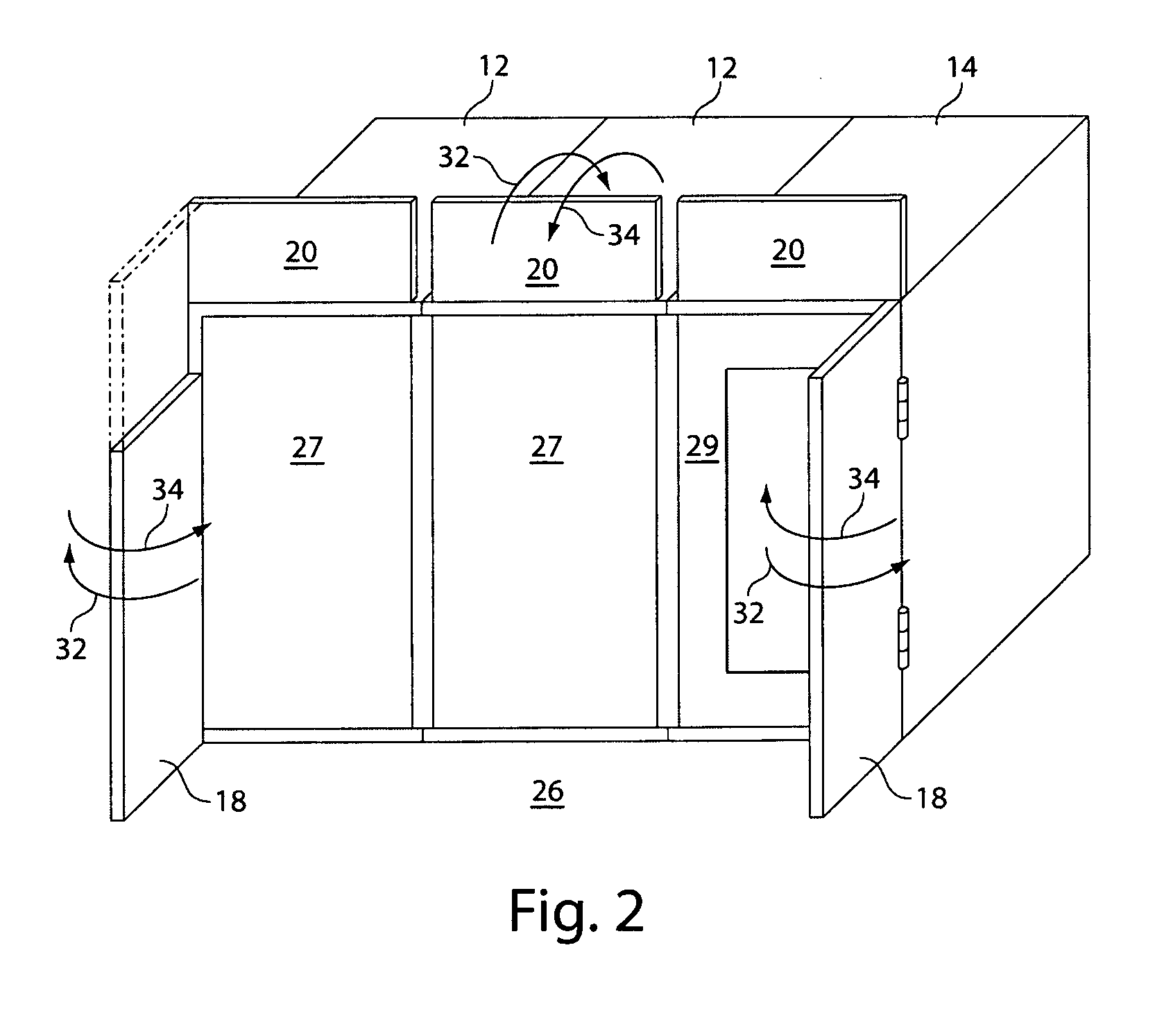
[0032] A further embodiment of the invention includes an air mixing restriction member for use in a
data center having a plurality of racks, each of the racks having a front face and a back face, wherein the racks are arranged in a first row and a second row such that the front faces of the racks of the first row face the front faces of the racks of the second row, wherein a cool
aisle is formed between the first row and the second row, the air mixing restriction member comprising a first planar portion coupled to a rack in the first row having a height substantially the height of the rack and configured to span most, but less than all, of the distance between the first row and the second row, a second planar portion coupled to a rack in the second row, the rack in the second row located opposite from the rack in the first row, the second planar portion having a height substantially the height of the rack and configured to span a portion of the distance between the second row and the first planar portion, and an attachment mechanism connected to the planar portion, for connecting the first planar portion to the first rack and for connecting the second planar portion to the second rack, such that the first planar portion and the second planar portion substantially
restrict mixing of air in the cool
aisle from
ambient air.
[0034] Various features of the invention may provide one or more of the following capabilities. The cooling unit of the invention can be used in data centers that do not have raised floors, and provide improved efficiency over
raised floor data centers. The cooling unit of the invention provides localized cooling solutions for matching the cooling needs of particular locations. Existing data centers can be modified to include aspects of the invention.
Cooling units can be added or removed depending on the cooling needs of a particular data center.
Cooling units can remain in position, but be modified to direct cooled air in a different direction or in more than one direction. A data room employing the cooling
system can operate with little or no modification to its structure, i.e., data center lighting, sprinkler systems, security systems, etc., do not require modification when a cooling unit is added or removed from the data center.
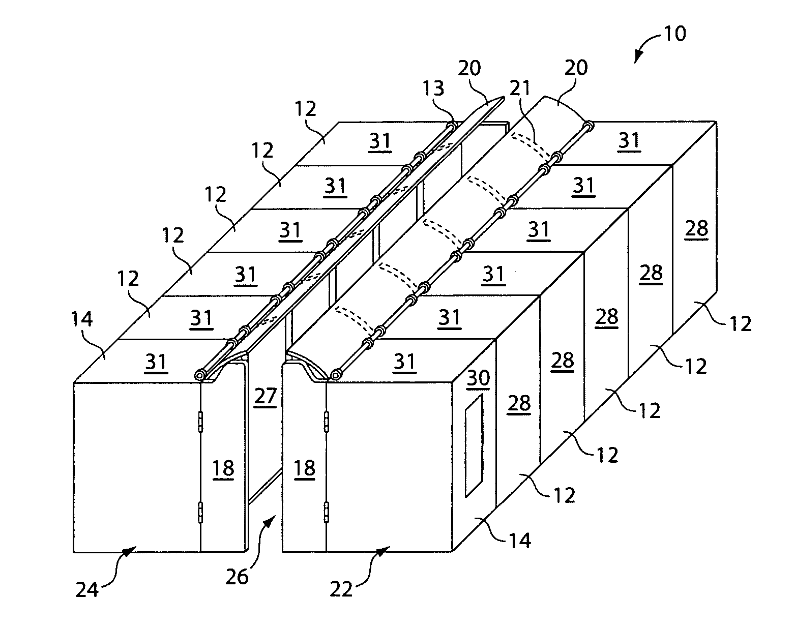
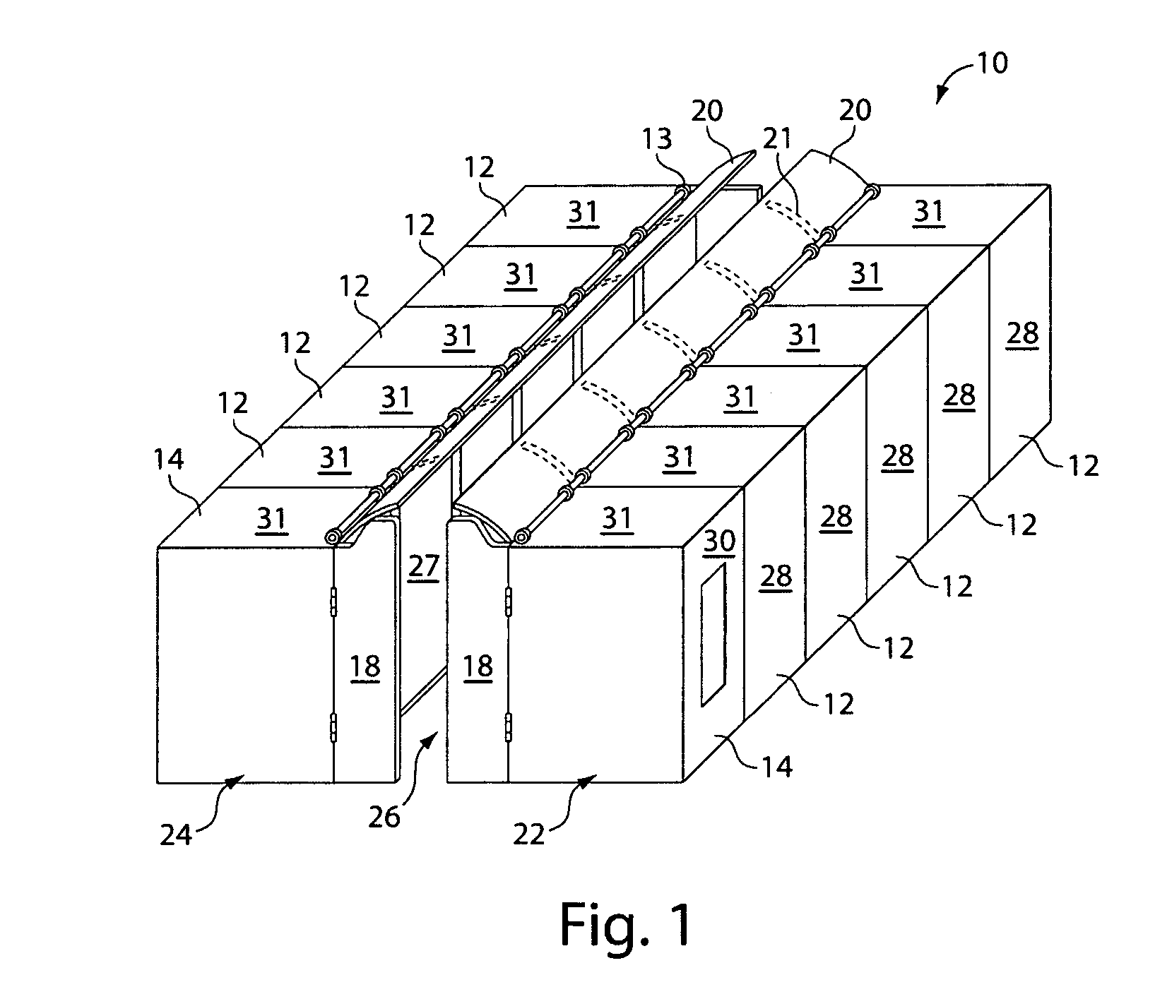
[0035] Further, the cooling
system of the invention is efficient. The invention allows for less opportunity for mixing of cold and hot air in a data center. The addition of upper restriction panels to the
cooling units and equipment racks, and the addition of
doors to the data rack rows creates a longer, more restrictive path that assists in preventing or restricting the hot air and the cool air from mixing. The cooling unit operates at a higher
inlet temperature. The invention allows realization of higher capacity relative to traditional, remotely located
cooling units. Cooling is substantially even from the top of racks to the bottom of the racks, allowing use of substantially the full height of a rack. Furthermore, the invention reduces the need for humidification / de-humidification.

