Cooler for electronic equipment

a technology of electronic equipment and cooling device, which is applied in the direction of lighting and heating apparatus, instruments, and the details of semiconductor/solid-state devices, etc., can solve the problems of reducing cooling efficiency, unable to secure the heat radiation area therein, and difficult to achieve a smaller thickness of the cooling device, so as to reduce the pressure transmitted from the pump, improve the cooling efficiency, and reduce the rate of liquid flow

Inactive Publication Date: 2006-06-29
NEC CORP
View PDF11 Cites 50 Cited by
  • Summary
  • Abstract
  • Description
  • Claims
  • Application Information

AI Technical Summary

Benefits of technology

[0009] Further, during the circulation of the refrigerant through the passage having a closed structure, a temperature change within the electronic equipment or a pressure change in the passage may collect the oxygen etc. included in the liquid to form air bubbles therein. If the air bubbles enter the pump chamber due to the liquid circulation, there arises a problem in that the presence of the air bubbles incurs absorption of pressure, reduces the pressure transmitted from the pump, and thus reduces the rate of liquid flow. Fu...

Problems solved by technology

The conventional technique described in the above publication has the configuration wherein the refrigerant is circulated through the tube disposed on the bottom of the personal computer body, an thus a sufficient heat radiation area cannot be secured therein.
Accordingly, there is a problem in that it only achieves a lower cooling efficient and it is difficult to achieve a smaller thickness for the cooling device.
In addition, the refrigerant is likely to leak from the connection between the pump and the tube in the conventional technique, and there is a higher possibility that the leakage ...

Method used


Image

  • Cooler for electronic equipment
  • Cooler for electronic equipment
  • Cooler for electronic equipment

Examples


first embodiment

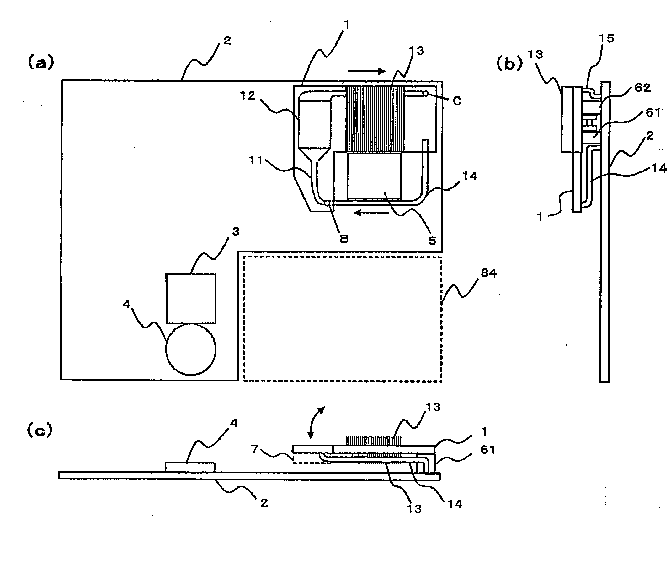
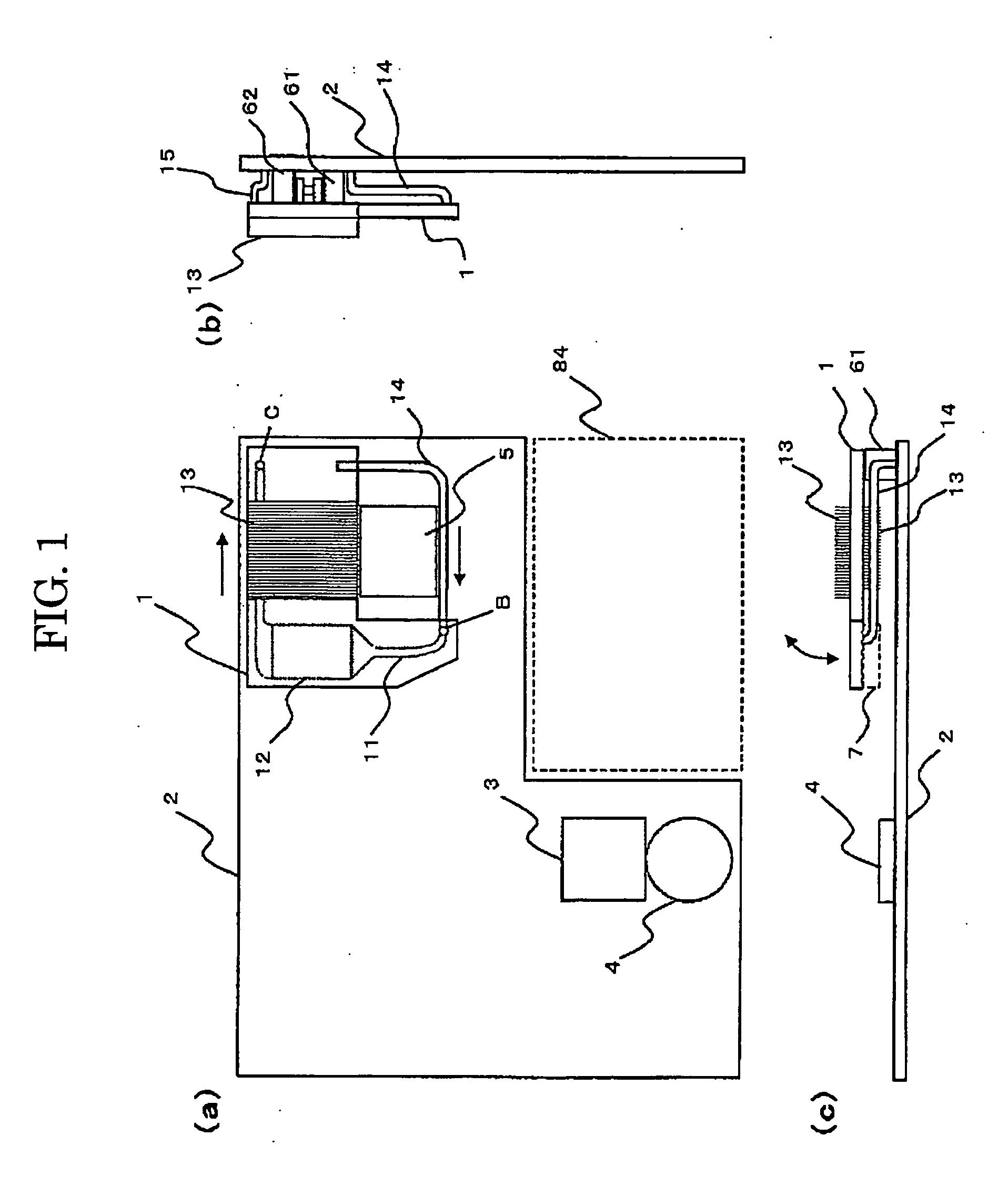
[0058] Referring to FIG. 1, a cooling device for an electronic equipment includes a first cooling panel 1, a second cooling panel 2, and coupling members 61, 62, which couple together the first cooling panel 1 and second cooling panel 2, and bear the first cooling panel 1 for allowing closing and opening movement thereof with respect to the second cooling panel 2 in the direction of arrows shown in FIG. 1(c). The present invention is applied to the second cooling panel 2.

[0059] The cooling device has a function of cooling the heating parts 7, such as CPU or other heating bodies generating heat, by circulating refrigerant such as water and antifreeze liquid through the passage, which is formed in the first cooling panel 1 and second cooling panel 2. The numeral 84 shown in FIG. 1 denotes a battery, and the second cooling panel 2 in the cooling device for the electronic equipment has a shape that does not overlap the area for the battery 84. The shape of the first cooling panel 1 and...

second embodiment

[0125] Next, a cooling device for an electronic equipment according to the present invention will be described. With reference to FIG. 26 first, the simple structure of a standing-rest-type reservoir 411 will be described. In the cooling device shown in the same drawing, the cooling panel (substrate) 20 has an integral body and includes therein a groove 231 configuring the passage (21). In addition, the passage 21 extending in a two-dimensional plane is provided with a laid-down-type reservoir 4 and the standing-rest-type reservoir 411 along the passage. Thus, the present cooling device can be used in a standing posture, for example, with the top side shown in FIG. 26 being the upside in the vertical direction and the bottom side shown in FIG. 26 being the downside in the vertical direction. The standing-rest-type reservoir 411 plays the roll for alleviating the pressure change in the passage against the expansion or compression caused by the temperature change of the refrigerant, a...

third embodiment

[0135]FIG. 28(a) shows a second cooling panel in the present invention. In this embodiment, the cooling device includes only a single cooling panel 2, and a piezoelectric pump 3 is supported on the top heat radiation plate of the cooling panel 2. The cooling panel 2 is provided with a passage 21 wherein struts 22 are formed in the central position, and the passage 21 is wobbled. The passage 21 is provided with the standing-rest-type reservoir 411 inserted and formed within the cooling panel 2, and the laid-down-type reservoir 4 located on the top heat radiation plate.

[0136]FIG. 28(b) is a side view of the cooling device of the present embodiment. The cooling panel 2 is formed by bonding together the bottom heat radiation plate 23 and the top heat radiation plate 24. Onto the top heat radiation plate 24 of the cooling panel are fixed the piezoelectric pump 3 and laid-down-type reservoir 4, whereas onto the bottom heat radiation plate 23 is fixed the air-cooled fin 13. Although not sh...


PUM


Abstract

A cooling device includes a cooling panel wherein a passage is formed by bonding together a bottom heat radiation plate having a groove formed therein and a top heat radiation plate, and a circulation pump circulating refrigerant within the passage. The top heat radiation plate is provided with an outlet port through which the refrigerant flows out from the passage to the circulation pump and an inlet port through which the refrigerant flows in from the circulation pump to the passage. The circulation pump is fixed onto the top heat radiation plate of the cooling panel so that the suction port and discharge port are aligned with the outlet port and inlet port, respectively.

Description

TECHNICAL FIELD [0001] The present invention relates to a cooling device for an electronic equipment and, more particularly, to a cooling device for an electronic equipment, suitable to cooling a heating part, such as a CPU, mounted on a notebook personal computer. BACKGROUDN ART [0002] Along with the increase in the amount and speed of processing, heating parts having a larger power dissipation, such as a CPU, are installed in the recent electronic equipment, such as a personal computer, and the amount of heat generated by the heating parts is more and more increasing. In these electronic equipment, the variety of electronic parts used therein generally have an operating temperature limit due to the temperature dependency of the heat-resistance reliability and operating characteristic. Thus, it is an urgent subject to establish the technique for efficient radiation of the heat generated within the electronic equipment toward the outside thereof. [0003] In general, the electronic eq...

Claims


Application Information

Patent Timeline
IPC IPC(8): H05K7/20B81B3/00F25B1/00G06F1/20H01L23/473
CPCH01L23/473H01L2924/3011H01L2924/0002H01L2924/00
Inventor MIKUBO, KAZUYUKIKITAJO, SAKAEOCHI, ATSUSHIYAMAMOTO, MITSURU
Owner NEC CORP
Why Eureka
Try Eureka