
Light-emitting device, and illumination apparatus and display apparatus using the light-emitting device

a technology of light-emitting devices and illumination apparatus, which is applied in the direction of instruments, lighting and heating apparatus, semiconductor lasers, etc., can solve the problems of insufficient light output efficiency, inferior color rendering properties of light-emitting devices, and -emitting devices having such structures, etc., and achieve high light output efficiency

Active Publication Date: 2006-06-29
SHARP FUKUYAMA LASER CO LTD
View PDF13 Cites 89 Cited by
  • Summary
  • Abstract
  • Description
  • Claims
  • Application Information

AI Technical Summary

Benefits of technology

[0008] An object of the present invention is to provide a light-emitting device having high light output efficiency and an illumination apparatus and a display apparatus using the light-emitting device.
[0015] According to the present invention, a light-emitting device having high light output efficiency and an illumination apparatus and a display apparatus using the light-emitting device can be provided.

Problems solved by technology

The former light-emitting device has an inferior color rendering property because it includes less red component, but high light emission efficiency is expected since it has only a small loss regarding color conversion (a Stokes loss).
The light-emitting device having such structure, however, still has insufficient light output efficiency, and therefore development of a light-emitting device having higher light output efficiency has been desired.

Method used


Image

  • Light-emitting device, and illumination apparatus and display apparatus using the light-emitting device
  • Light-emitting device, and illumination apparatus and display apparatus using the light-emitting device
  • Light-emitting device, and illumination apparatus and display apparatus using the light-emitting device

Examples


first embodiment

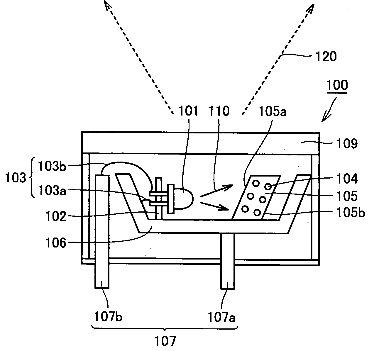
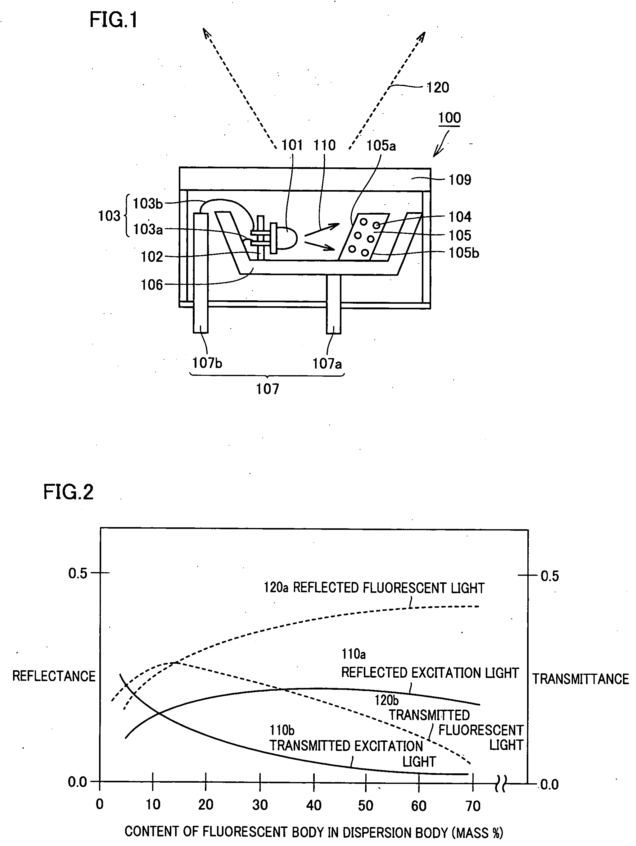
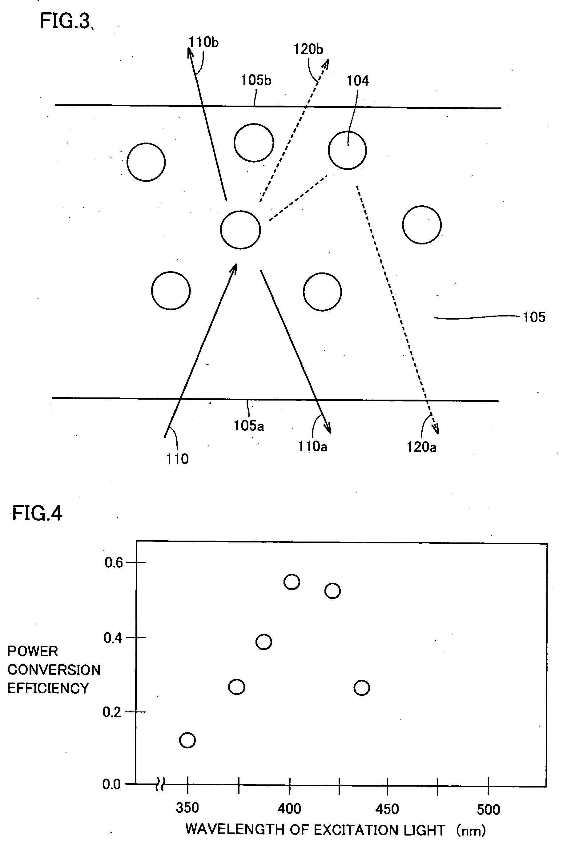
[0034] Referring to FIG. 1, an embodiment of a light-emitting device 100 according to the present invention includes a light-emitting element 101 emitting excitation light 110 for exciting a fluorescent body 104, a dispersion body 105 having fluorescent body 104 dispersed therein, which fluorescent body 104 emits fluorescent light 120 having a wavelength different from that of excitation light 110, and a lead frame 106 holding light-emitting element 101 and dispersion body 105, wherein at least a portion of the fluorescent light emitted from fluorescent body 104 in dispersion body 105 is output to the outside from a side 105a of dispersion body 105 receiving the excitation light.

[0035] More specifically, in light-emitting device 100 of this embodiment, a shell-shaped nitride-based semiconductor light-emitting diode having a light emission peak wavelength of 405 nm as light-emitting element 101 is fixed to lead frame 106 with a support body 102. The nitride-based semiconductor light...

embodiment 1a

[0036] A more specific embodiment of the first embodiment is shown in this embodiment. Referring to FIG. 1, dispersion body 105 used in light-emitting device 100 of this embodiment is formed by dispersing red, green and blue fluorescent bodies, which are excited with excitation light having a light emission peak wavelength of 405 nm emitted from the nitride-based semiconductor light-emitting diode (light-emitting element 101), in an epoxy resin plate having a thickness of 5 mm in such a ratio that, a white color indicated with chromaticity coordinates of x=0.32 and y=0.32 is formed with red, green and blue fluorescent light respectively emitted from the fluorescent bodies. Herein, Y2O2S:Eu3+ having a fluorescent light peak wavelength of 635 nm is used as the red fluorescent body, ZnS:Cu, Al having a fluorescent light peak wavelength of 520 nm is used as the green fluorescent body, and (Sr, Ca, Ba, Mg)10(PO4)6:Eu2+ having a fluorescent light peak wavelength of 480 nm is used as the b...

embodiment 1b

[0047] Another specific embodiment of the first embodiment is shown in this embodiment. Referring to FIG. 1, light-emitting device 100 of this embodiment is similar to the light-emitting device of the embodiment 1A except that SrAl2O4:Eu2+, a green fluorescent body having a fluorescent light peak wavelength of 520 nm, is used as fluorescent body 104 in dispersion body 105. FIG. 5 shows a relation between a content of fluorescent body 104 in dispersion body 105 in the light-emitting device of this embodiment and intensity of each of reflected fluorescent light 120a and transmitted fluorescent light 120b from fluorescent body 104 as well as whole fluorescent light 120 which is a sum of the reflected fluorescent light and the transmitted fluorescent light. In FIG. 5, intensity of fluorescent light is indicated as a standard value which is relative intensity when intensity of excitation light 110 used to irradiate the fluorescent body is set to 1.

[0048] Referring to FIG. 5, in terms of...


PUM


Abstract

A light-emitting device including a light-emitting element emitting excitation light for exciting a fluorescent body, a dispersion body having the fluorescent body dispersed therein, which fluorescent body emits fluorescent light having a wavelength different from that of the excitation light, and a lead frame holding the light-emitting element and the dispersion body, wherein at least a portion of the fluorescent light emitted from the fluorescent body in the dispersion body is output to the outside from a side of the dispersion body receiving the excitation light. With this, a light-emitting device having high light output efficiency and an illumination apparatus and a display apparatus using the light-emitting device are provided.

Description

[0001] This nonprovisional application is bsased on Japanese Patent Applications Nos. 2004-379247 and 2005-348177 filed with the Japan Patent Office on Dec. 28, 2004 and Dec. 1, 2005, respectively, the entire contents of which are hereby incorporated by reference. BACKGROUND OF THE INVENTION [0002] 1. Field of the Invention [0003] The present invention relates to a light-emitting device including a fluorescent body which absorbs excitation light from a light-emitting element and emits light having a wavelength different from that of the excitation light, and to an illumination apparatus and a display apparatus using the light-emitting device. [0004] 2. Description of the Background Art [0005] Recently, a solid-state illumination technique (a semiconductor illumination technique) has been rapidly developed, which implements emission of light of white or other colors using a fluorescent body and a solid-state light-emitting element as an excitation light source for exciting the fluore...

Claims


Application Information

Patent Timeline
Patent Type & Authority Applications(United States)
IPC IPC(8): F21V23/02H01L33/06H01L33/30H01L33/50H01L33/60H01S5/022H01S5/343
CPCB82Y20/00F21K9/00G02F1/133603H01L33/501H01L33/507H01S5/005H01S5/02292H01S5/2009H01S5/22H01S5/34333H01L2224/48091H01L2224/48247H01L2224/8592H01L2924/181H01S5/02255H01S5/0087H01L2924/00014H01L2924/00012
Inventor MORIOKA, TATSUYAKAWASAKI, OSAMU
Owner SHARP FUKUYAMA LASER CO LTD
Learn More