Light source device, lighting device and liquid crystal display device

a technology of liquid crystal display and light source device, which is applied in the direction of lighting and heating apparatus, instruments, transportation and packaging, etc., can solve the problems of damage to peripheral components and damage to peripheral components, and achieve stable light emission characteristics, prevent dielectric breakdown of atmospheric gas, and high reliability

Inactive Publication Date: 2006-06-29
PANASONIC CORP
View PDF6 Cites 13 Cited by
  • Summary
  • Abstract
  • Description
  • Claims
  • Application Information

AI Technical Summary

Benefits of technology

[0010] It is an object of the present invention to solve the problems caused by the gap inevitably generated between the external electrode and the outer face of the bul

Problems solved by technology

The gas molecules of the atmospheric gas ionized by the dielectric breakdown cause damages on peripheral members.
For examp

Method used


Image

  • Light source device, lighting device and liquid crystal display device
  • Light source device, lighting device and liquid crystal display device
  • Light source device, lighting device and liquid crystal display device

Examples


first embodiment

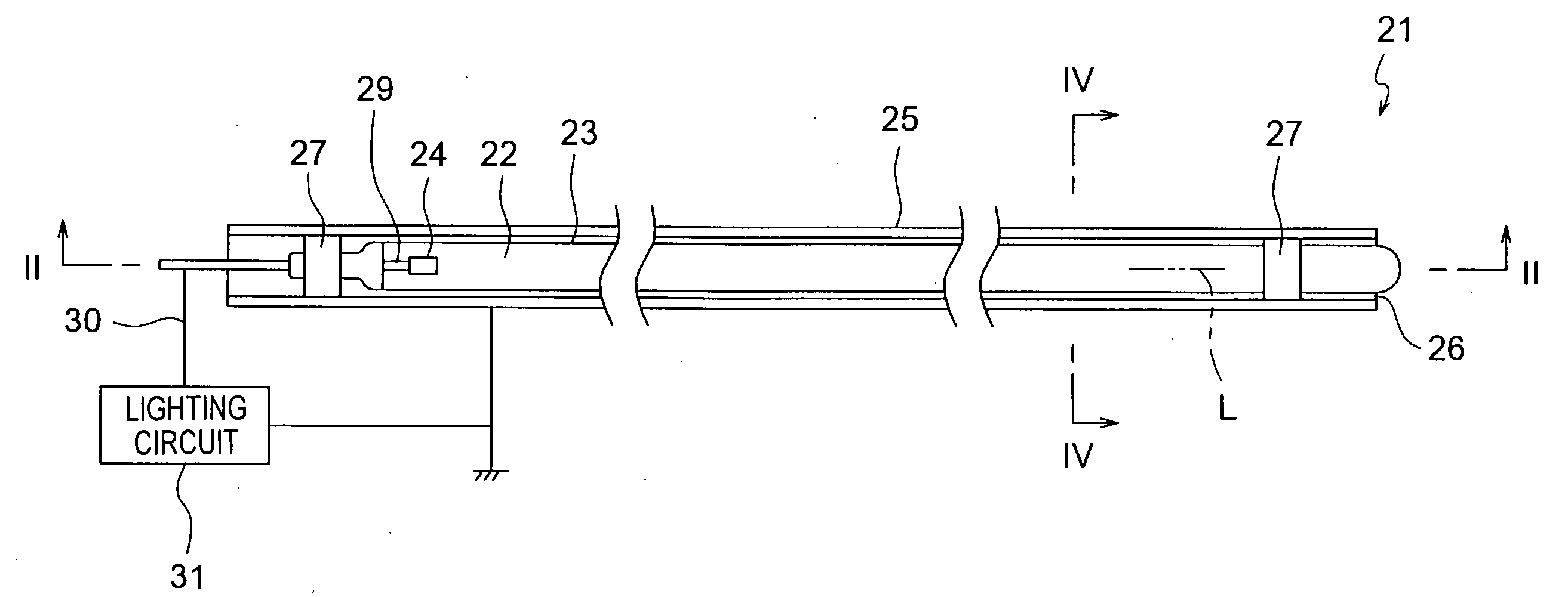
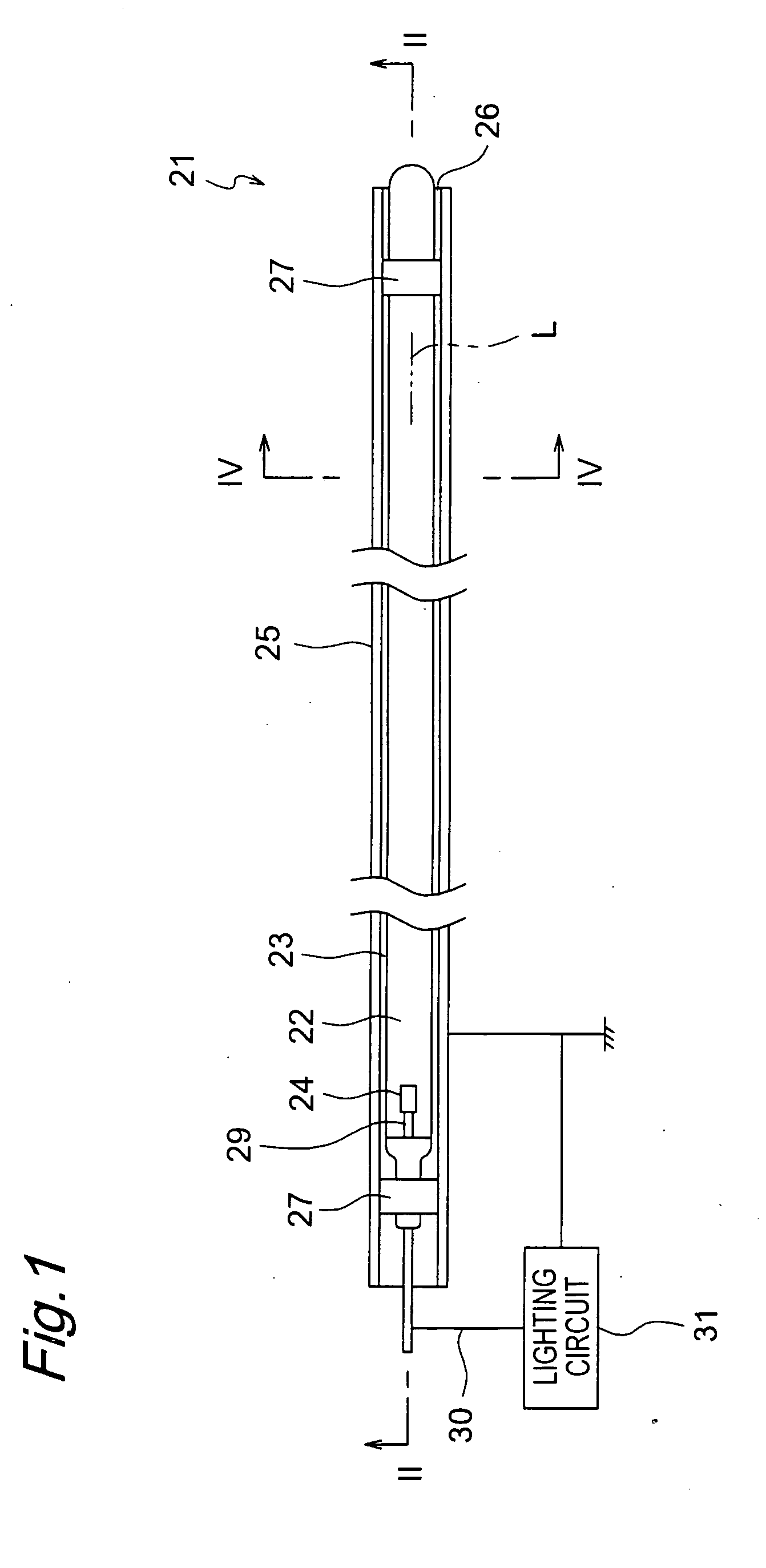
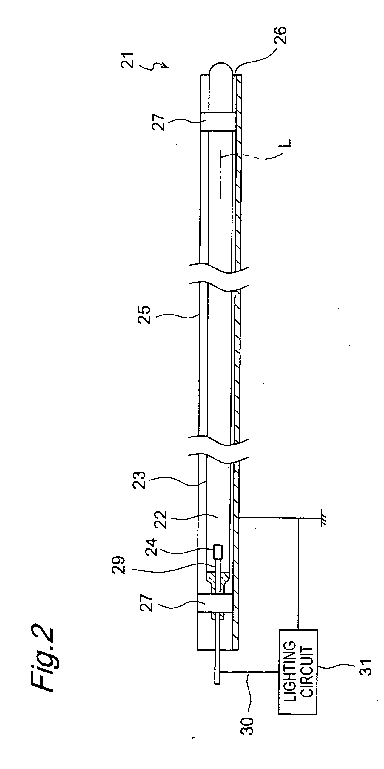
[0096] FIGS. 1 to 6 show a lamp or light source device 21 according to a first embodiment of the present invention. The light source device 21 comprises a air tight vessel or bulb 23 of which an inside functions as a discharge space 22, a discharge medium (not shown) sealed inside the bulb 23, an internal electrode (first electrode) 24, and an external electrode (second electrode) 25. The light source device 21 further comprises two holder members 27 for holding the external electrode 25 so that the external electrode 25 is opposed to the bulb 23 with a predetermined distance X1 of a space 26 therebetween. The light source device 21 further comprises a lighting circuit 31 for applying high frequency voltage to the discharge medium.

[0097] The bulb 23 has an elongated straight tubular shape extending along an axis line L thereof. As shown in FIGS. 3 and 4, a cross-section of the bulb 23 perpendicular to the longitudinal axis line L has a circular shape. The cross-sectional shape of t...

second embodiment

[0160] The light source device 21 according to a second embodiment of the present invention shown in FIGS. 14A and 14B has the external electrode 25 having a strip-like shape with constant width. The space 26 is created between the external electrode 25 and the outer face of the bulb 23, and the distance X1 of the space 26 is set to be longer than the shortest distance X1L defined by the equation (13).

[0161] Since the other arrangements and functions of the second embodiment are the same as those of the first embodiment, the same elements are denoted by the same reference symbols, and descriptions thereof are omitted.

third embodiment

[0162] In a third embodiment shown in FIGS. 15A and 15B, a plurality of external electrodes 25 are disposed at intervals along the axis line L of the bulb 23. Specifically there are two rows of a plurality of external electrodes 25 disposed at intervals along the direction of the axis line L. Each of external electrodes 25 is held by a holder member not illustrated, so as to be opposed to the outer surface of the bulb 23 with the space 26 therebetween.

[0163] Since the other arrangements and functions of the third embodiment are the same as those of the first embodiment, the same elements are denoted by the same reference symbols, and descriptions thereof are omitted.


PUM


Abstract

The light source device has a bulb, a discharge medium containing rare gas sealed inside the bulb, an internal electrode disposed inside the bulb, and an external electrode disposed outside the bulb. A holder member holds the external electrode so that the external electrode is opposed to the bulb with a predetermined distance of a space therebetween.

Description

[0001] This is a continuous application of International Application No. PCT / JP2004 / 012283, filed Aug. 26, 2004. BACKGROUND OF THE INVENTION [0002] The present invention relates to a light source device comprising a bulb, a discharge medium mainly composed to a rare gas sealed inside the bulb, and an electrode for exciting the discharge medium. The present invention also relates to a lighting device, such as a back light device, comprising this light source device, and a liquid crystal device comprising this back light device. [0003] Recently, a research on a light source device that does not use mercury (hereafter referred to as mercury-less type) as a lamp or light source device used for a back light device of a liquid crystal display device is actively progressing, in addition to a research on a light source device using mercury for such usage. The mercury-less type light source device is preferable due to low fluctuation of light emission intensity along with time variation of t...

Claims


Application Information

Patent Timeline
IPC IPC(8): F21V15/00F21S2/00F21V8/00F21V23/00F21Y103/00G02F1/13357H01J65/00H05B41/24
CPCH01J65/00H05B41/24
Inventor HIROHASHI, MASAKISHIMIZU, NOBUHIROYAMAMOTO, NORIKAZUSHIGETA, TERUAKIMATSUBAYASHI, YOKO
Owner PANASONIC CORP
Why Eureka
Try Eureka