Fluid delivery system and flow control therefor

a flow control and fluid technology, applied in the field of fluid delivery systems and flow control therefor, can solve the problems of poor flow rate accuracy of pump and similar devices known in the art, tight material/geometry control, and relatively sophisticated mechanical components. cost-effective

Inactive Publication Date: 2006-06-29
BAXTER INT INC
View PDF45 Cites 41 Cited by
  • Summary
  • Abstract
  • Description
  • Claims
  • Application Information

AI Technical Summary

Benefits of technology

[0013] In one form, an improved fluid delivery system benefits from a closed-loop control process that uses flow rate information to ensure that the desired flow rate is substantially achieved. Further, in one form, such a system is constructed using one or more micro-fabrication and / or molding techniques allowing for a cost-effective, disposable administration set.

Problems solved by technology

Heretofore, infusion pumps and similar devices known in the art have typically not provided closed-loop flow control to achieve precise delivery rates.
A typical accuracy of such systems, in terms of flow rate, is normally no better than about + / −5%, and requires relatively sophisticated (and costly) mechanical components and tight material / geometry controls (e.g., of the tubing) to achieve that rate.
Further, non-ambulatory pumps often do not achieve a five percent accuracy range at low flow rates or over longer time periods due to modification of the tubing material over time.
This deformation process changes the elastic recovery properties of the tube, resulting in changes in the volumetric output of the pump over time.
While such systems reflect improvements in the art, they do not control fluid delivery in view of actual flow rates.
In some circumstances, therefore, such systems would not provide as accurate information and tight control based on actual fluid flow rate data.
Such conventional PD sensors, however, are not well-suited for use in high-precision medical fluid delivery systems.
Moreover, conventional manufacturing techniques tend to be expensive and, therefore, are not well-suited for use in manufacturing disposable items.
It is believed, however, that LIGA-based micropumps have never been made available commercially.
Cost is one substantial drawback of LIGA; it is believed that there are relatively few synchrotron devices (e.g., 10-15 devices) in the world.
Accordingly, LIGA is fairly limited in its applicability for directly manufacturing low cost devices.

Method used


Image

  • Fluid delivery system and flow control therefor
  • Fluid delivery system and flow control therefor
  • Fluid delivery system and flow control therefor

Examples


Embodiment Construction

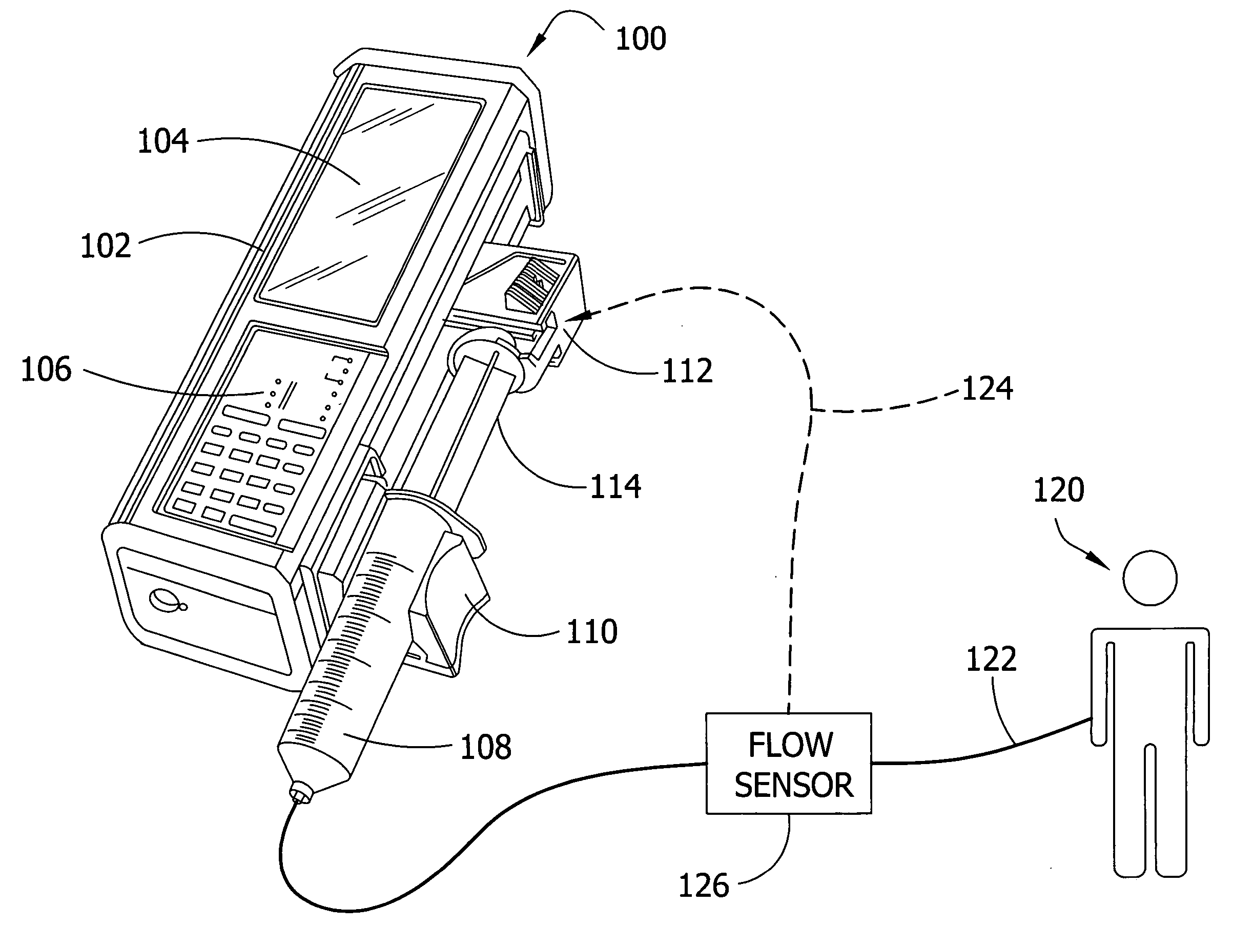
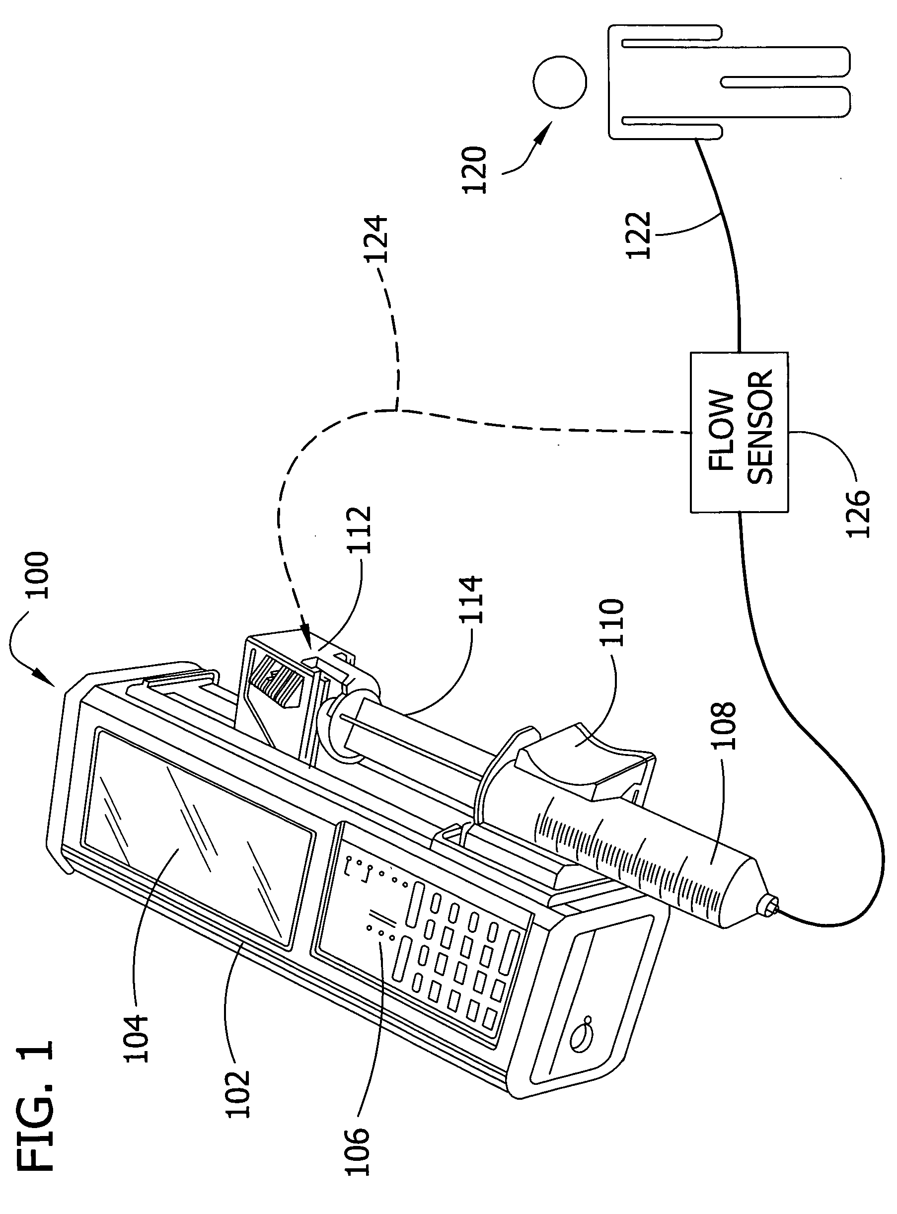
[0034] Referring now to the drawings, FIG. 1 illustrates one embodiment of an infusion pump 100 suitable for use in connection with aspects of the present invention. In the illustrated example, the infusion pump 100 comprises a syringe-type infusion pump. Infusion pump 100 includes a housing 102, a display screen 104, and a control panel 106. The control panel 106 and the display screen are used to enter set-point data for operating infusion pump 100 and for monitoring the operation of pump 100.

[0035] The infusion pump 100 also includes a syringe barrel 108 for holding a medical fluid to be administered. A barrel bracket 110 attaches the syringe barrel 108 is attached to the housing 102. A movable syringe driver 112 is also attached to housing 102 and is positioned in engagement with a syringe plunger 114. A driving mechanism within housing 102 is constructed and arranged so that the movable syringe driver 112 can drive syringe plunger 114 into (or out of) syringe barrel 108 in a c...


PUM


Abstract

A fluid delivery system having a closed-loop control process for delivering a medical fluid to a patient. A fluid infusion system includes a pump for delivering a fluid to a patient via an administration tube. A flow sensor associated with the administration tube provides an indication of the actual flow rate of fluid in the administration tube. Such a flow sensor may comprise a positive displacement flow sensor constructed using micro-fabrication and/or micro-molding techniques. A reader reads the actual flow rate signal and provides an indication to a controller for controlling the pump. The flow rate information can also be used for providing status information, such as the existence of a blockage in the fluid delivery system.

Description

BACKGROUND OF THE INVENTION [0001] 1. Field of the Invention [0002] The invention relates generally to delivering fluids to a patient and, particularly, to closed-loop flow control systems and methods for delivering medical fluids to a patient at a controlled delivery rate. [0003] 2. Description of the Prior Art [0004] A variety of fluid delivery systems are currently being used in the medical field for delivering medical fluids (containing medication, nutrition, saline, and so on) to human and veterinary patients. It is often desirable to administer such medical fluids at relatively precise delivery rates. In some cases, the rate of delivery may be exceptionally important. In recent years, it has also been found to be advantageous to use various types of infusion pumps to administer medical fluids automatically, over extended periods of time. A typical infusion pump delivers the medical fluid into the patient's venous system using a delivery channel which usually comprises an admin...

Claims


Application Information

Patent Timeline
Patent Type & Authority Applications(United States)
IPC IPC(8): A61M31/00A61M1/00A61M5/168A61M5/172
CPCA61M5/14236A61M5/16886A61M2205/0294A61M2205/0244A61M5/172G05D7/0676A61M5/168
Inventor JACOBSON, JAMES D.BUI, TUANGARCHOW, STEPHEN R.YARDIMCI, ATIFSLEPICKA, JAMES S.
Owner BAXTER INT INC
Why Eureka
Try Eureka