
Processing-subject cleaning method and apparatus, and device manufacturing method and device

Inactive Publication Date: 2006-07-06
SEIKO EPSON CORP
View PDF8 Cites 6 Cited by
  • Summary
  • Abstract
  • Description
  • Claims
  • Application Information

AI Technical Summary

Benefits of technology

[0010] The present invention has been made to solve the above problems in the conventional art, and an object of the invention is therefore to reduce the amounts of cleaning liquids and rinse liquid used as well as the energy consumption.
[0026] A device according to the invention is characterized by being manufactured by using one of the cleaning apparatuses described above. This makes it possible to reduce the amounts of cleaning agents and the energy that are consumed to manufacture the device, and to reduce loads on the environment and the device cost.

Problems solved by technology

As such, in the conventional cleaning, large amounts of cleaning liquids and rinse liquid are required because the entire substrate is cleaned.
Further, in the conventional cleaning, since the entire substrate is cleaned, stains, once removed by cleaning from portions where no patterns will be formed, may stick to pattern-forming portions, which makes it necessary to rinse off the stains stuck to the pattern-forming portions with a large amount of rinse liquid.
Thus, the cleaning of substrates requires much time and a great cost and puts heavy loads on the environment.
Furthermore, the conventional cleaning consumes much energy to maintain prescribed temperatures of large amounts of cleaning liquids and rinse liquid.
Therefore, cleaning equipment (cleaning facilities) is large sized and requires a large installation space.

Method used


Image

  • Processing-subject cleaning method and apparatus, and device manufacturing method and device
  • Processing-subject cleaning method and apparatus, and device manufacturing method and device
  • Processing-subject cleaning method and apparatus, and device manufacturing method and device

Examples


first embodiment

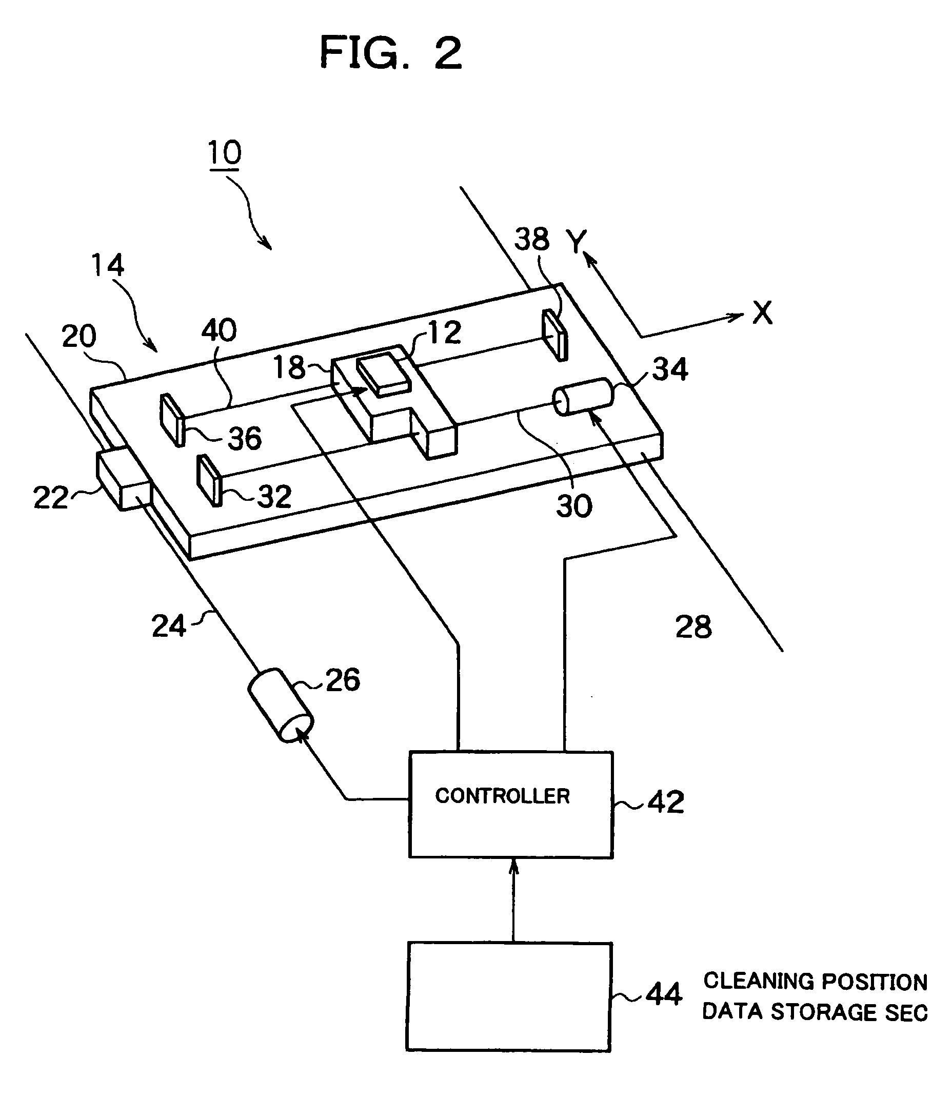
[0032]FIG. 2 is a perspective view, as viewed from below, of the important part of a cleaning apparatus according to the invention. As shown in FIG. 2, a cleaning apparatus 10 is equipped with a cleaning head 12, which will be described later in detail. Mounted on what is called an XY table 14, the cleaning head 12 can be moved parallel with the surface of a substrate of a semiconductor substrate, a glass substrate or the like (not shown in this figure), that is, the surface of a processing-subject.

[0033] The XY table 14 is composed of an X table 18 and a Y table 20 on which the X table 18 is mounted. A cleaning head 12 is fixed to the X table 18, and a liquid storage unit (not shown) in which a cleaning liquid, a rinse liquid etc. is stored, is mounted on the X table 18. On the other hand, mounted on a Z table (not shown), the Y table 20 can be moved together with the Z table in the vertical direction that is perpendicular to the surface of the Y table 20. A nut unit 22 that is pro...

second embodiment

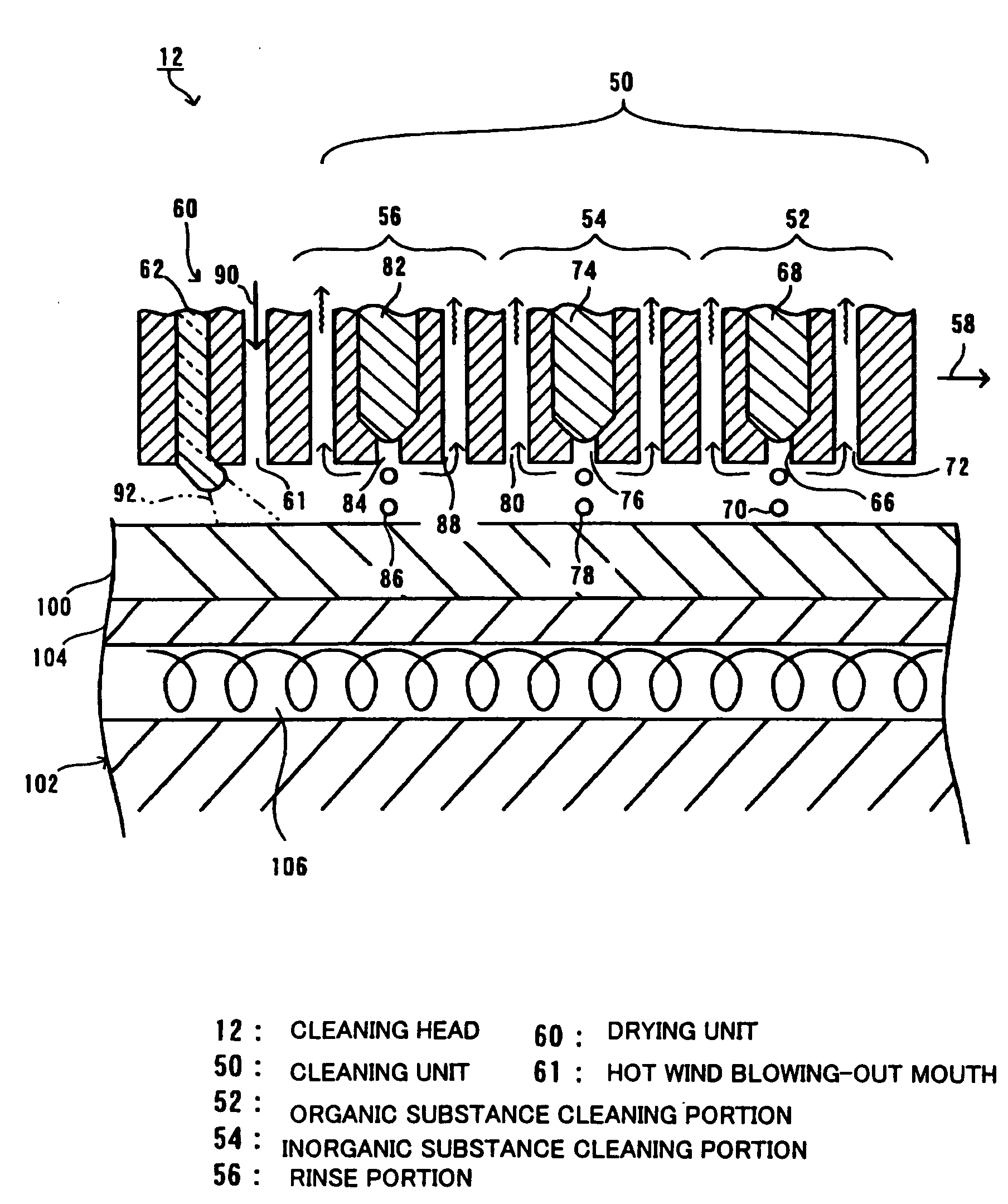
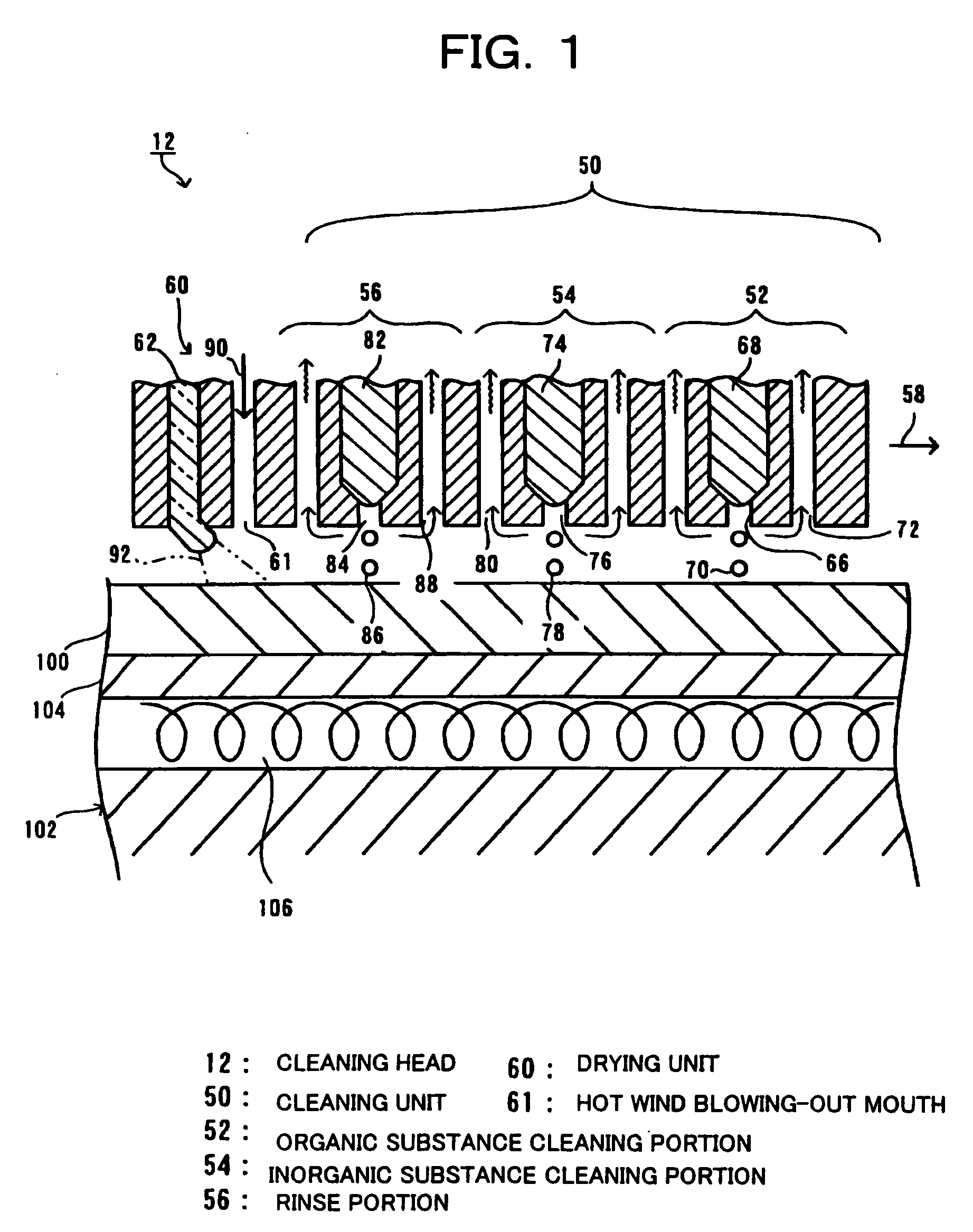
[0059]FIG. 4 illustrates an important part of a cleaning apparatus according to the invention and is a sectional view of a cleaning head. The cleaning head 120 according to the embodiment has a plurality of cleaning units 122, and a hot wind blowing-out mouth 61. Each cleaning unit 122 is composed of an organic substance cleaning portion 130, an inorganic substance cleaning portion 140, and a rinse portion 56 that are arranged in this order in a moving direction of the cleaning head 12 which is indicated by arrow 58.

[0060] The tip portion of the organic substance cleaning portion 130 assumes a triple-tube structure, in which a first liquid nozzle 134 for jetting out a first dissolving liquid 132 such as pure water in the form of fine particles 133, is provided at the center portion. In the organic substance cleaning portion 130, a first gas nozzle 136, for jetting out a first reactive gas 135 such as ozone capable of oxidizing organic substances, is provided around the first liquid ...


PUM

PropertyMeasurementUnit
Energyaaaaaaaaaa

Abstract

The invention reduces the amounts of cleaning liquids and rinse liquid used, as well as the energy consumption. A cleaning head has a plurality of cleaning units and a drying unit. An organic substance cleaning portion of each cleaning unit blows a first cleaning agent selectively over a portion to be cleaned of a substrate, and sucks reaction products etc. through a first suction mouth. An inorganic substance cleaning portion blows a second cleaning agent over the portion to be cleaned of the substrate from which organic substance have been removed, and sucks reaction products etc. through a second suction mouth. A rinse portion blows pure water the portion of the substrate from which inorganic substance have been removed, and sucks its vapor through a third suction mouth. The drying unit dries the substrate by blowing out a heated gas from a hot wind blowing-out mouth. A light guide illuminates the portion to be cleaned of the substrate with ultraviolet light, and thereby decomposes residual organic substances.

Description

[0001] This is a Division of application Ser. No. 10 / 366,664 filed Feb. 14, 2003. The entire disclosure of the prior application is hereby incorporated by reference herein its entirety.BACKGROUND OF THE INVENTION [0002] 1. Field of Invention [0003] The present invention relates to a method for cleaning a semiconductor substrate, a glass substrate or the like. In particular, the invention relates to a processing-subject cleaning method and apparatus suitable for cleaning a substrate on which patterns of circuit elements, interconnections, etc. are to be formed, and a device manufacturing method and a device. [0004] 2. Description of Related Art [0005] In general, in forming patterns to provide circuit elements etc. on a substrate such as a semiconductor substrate or a glass substrate, the patterns are formed after cleaning the substrate. This is because, for example, if organic or inorganic stains exist on the surface of a substrate, they may prevent formation of patterns or impair t...

Claims


Application Information

Patent Timeline
IPC IPC(8): C23G1/00B08B3/00B08B3/12B08B5/00B08B3/02B08B3/08C03C23/00H01L21/00H01L21/304
CPCB08B3/02B08B2203/0229C03C23/0075H01L21/67028H01L21/67051Y10S438/906
Inventor MORI, YOSHIAKI
Owner SEIKO EPSON CORP
Features
  • Generate Ideas
  • Intellectual Property
  • Life Sciences
  • Materials
  • Tech Scout
  • Unparalleled Data Quality
  • Higher Quality Content
  • 60% Fewer Hallucinations
Learn More