Method of manufacturing a needle assembly for use with a biopsy device

a biopsy device and manufacturing method technology, applied in the field of biopsy devices, can solve the problems of requiring significant time and expense to make and attach the needle, no single procedure is ideal for all cases, and the process known in the art for manufacturing these needles is often expensive and labor-intensive. achieve the effect of maintaining the necessary biomechanical properties and reducing the cost of manufacturing the biopsy needle devi

Inactive Publication Date: 2006-07-06
DEVICOR MEDICAL PROD
View PDF13 Cites 106 Cited by
  • Summary
  • Abstract
  • Description
  • Claims
  • Application Information

AI Technical Summary

Benefits of technology

[0009] The process of the current invention overcomes the above-noted and other deficiencies of the prior art by providing a process for manufacturing a biopsy needle device that reduces the number of components that must be separately manufactured and assembled, thereby reducing the cost of manufacturing the biopsy needle device while maintaining the necessary biomechanical properties.

Problems solved by technology

The type of biopsy used depends mainly on various factors present in the patient, and no single procedure is ideal for all cases.
While biopsy needles of the type described above are useful in obtaining tissue samples, the processes known in the art for manufacturing these needles are often expensive and labor-intensive due to the number of components and steps involved.
These sharpened tips often have small components and / or features that require significant time and expense to make and attach to the needle.
Even if a more reliable method of attaching the mounting component to the needle is used, such as induction heating or heat staking, such methods still involve the added expense necessitated by the extra assembly equipment as well as the steps of manufacturing the mounting component and attaching it to the needle.

Method used


Image

  • Method of manufacturing a needle assembly for use with a biopsy device
  • Method of manufacturing a needle assembly for use with a biopsy device
  • Method of manufacturing a needle assembly for use with a biopsy device

Examples


Embodiment Construction

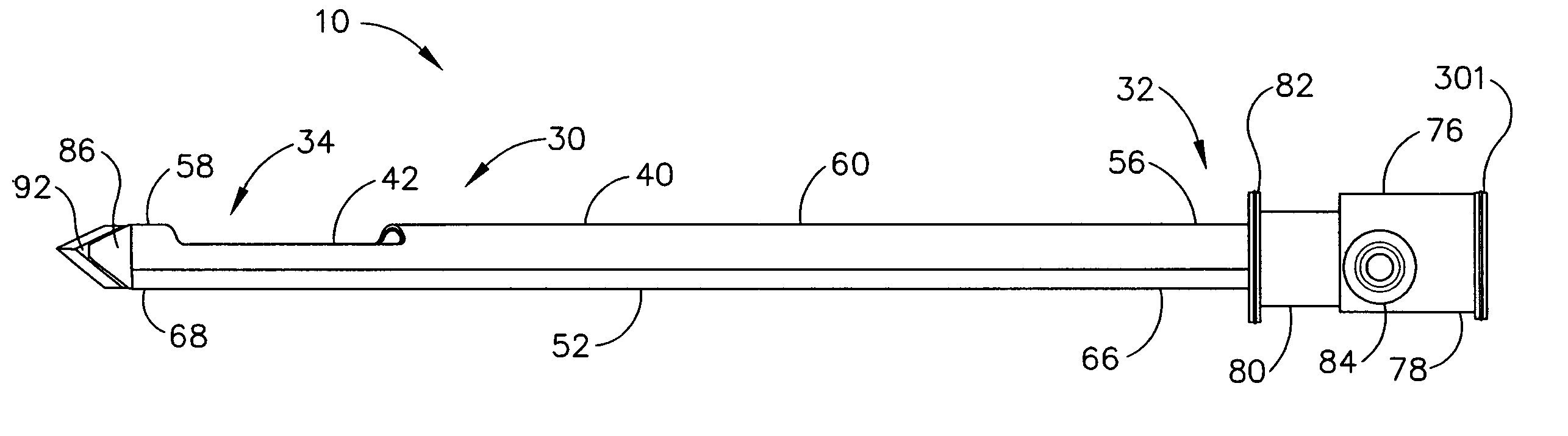
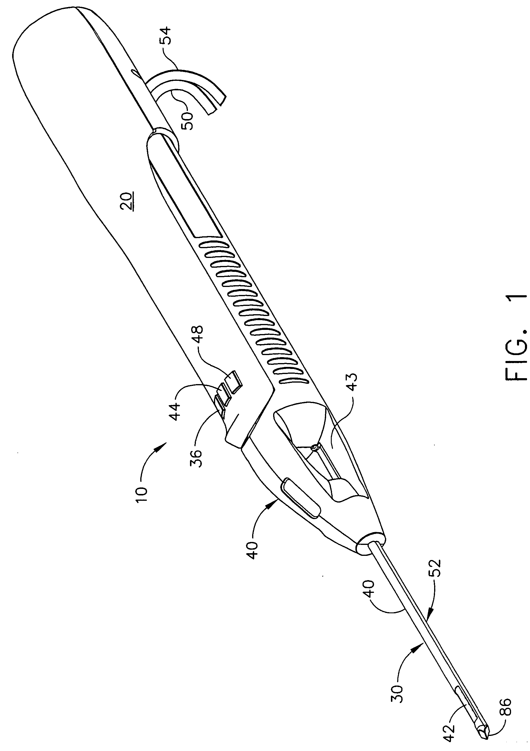
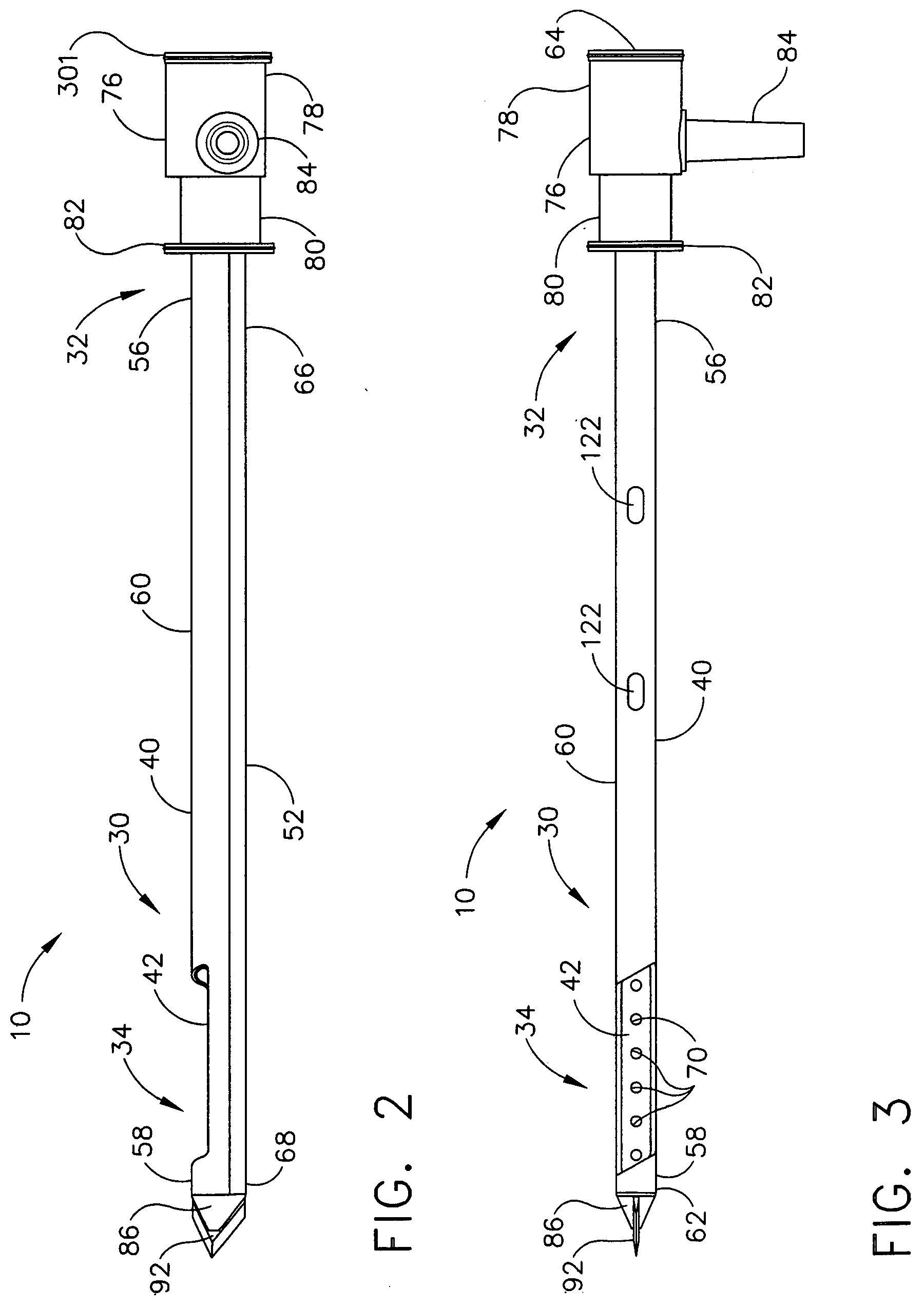
[0027]FIG. 1 shows a hand-held vacuum-assisted biopsy device 10 comprising a handle 20 detachably connected to a needle assembly 30 having a proximal portion 32 and a distal portion 34 manufactured according to a version of the process of the current invention. Together, they constitute a lightweight, ergonomically-shaped, hand-manipulated biopsy device 10. In one aspect, needle assembly 30 may be part of a disposable probe that may mount on handle 20. In one aspect, hand-held biopsy device 10 may be used in conjunction with an ultrasound to guide needle assembly 30. Since handle 20 may be manipulated by the operator's hand, the operator may steer needle assembly 30 with great freedom towards the tissue mass of interest. The surgeon has tactile feedback while doing so and may therefore ascertain to a significant degree the density and hardness of the tissue being encountered. In addition, handle 20 may be held approximately parallel to the chest wall of a patient for obtaining tissu...


PUM

PropertyMeasurementUnit
liquid crystalaaaaaaaaaa
melt flow indexaaaaaaaaaa
vacuumaaaaaaaaaa

Abstract

An improved process for manufacturing a biopsy needle assembly is provided. The process may comprise the steps of forming an aperture for receiving tissue to be sampled in an exterior surface of an elongated tube for receiving a cutter, wherein the elongated tube comprises a proximal portion and a distal portion; forming a hole in the exterior surface of the elongated tube; and applying a coating of material over the elongated tube to form a lumen for receiving vacuum on the exterior surface of the elongated tube, wherein the hole in the exterior surface of the elongated tube provides communication between an interior of the elongated tube and an interior of the lumen. In one version, the elongated tube may be placed in a mold configured to form the vacuum lumen when material is injected into the mold. A proximal hub may advantageously be formed by overmolding.

Description

FIELD OF THE INVENTION [0001] The present invention is related generally to biopsy devices and, more particularly, to an improved process of manufacturing a needle assembly for use with a biopsy device for acquiring a tissue sample. BACKGROUND OF THE INVENTION [0002] The diagnosis and treatment of patients with cancerous tumors, pre-malignant conditions, and other disorders has long been an area of intense investigation. Non-invasive methods for examining tissue include palpation, thermography, PET, SPECT, Nuclear imaging, X-ray, MRI, CT, and ultrasound imaging. When the physician suspects that tissue may contain cancerous cells, a biopsy may be done either in an open procedure or in a percutaneous procedure. For an open procedure, a scalpel is used by the surgeon to create a large incision in the tissue in order to provide direct viewing and access to the tissue mass of interest. Removal of the entire mass (excisional biopsy) or a part of the mass (incisional biopsy) is performed. ...

Claims


Application Information

Patent Timeline
Patent Type & Authority Applications(United States)
IPC IPC(8): B21G1/00
CPCA61B10/0275Y10T29/49885Y10T156/1056A61B10/0283A61B10/02
Inventor BECKMAN, ANDREW T.KASCAK, NOREENREICHEL, LEELUDZACK, MICHAEL
Owner DEVICOR MEDICAL PROD
Why Eureka
Try Eureka