Isolation of short-circuited sensor cells for high-reliability operation of sensor array

a sensor array and short-circuited technology, applied in the field of arrays of sensors, can solve the problems of achieve the effects of negligible effect on imaging performance, simple and cost-effective, and substantially degrading imaging performan

Active Publication Date: 2006-07-06
GENERAL ELECTRIC CO
View PDF4 Cites 76 Cited by
  • Summary
  • Abstract
  • Description
  • Claims
  • Application Information

AI Technical Summary

Benefits of technology

[0008] The invention provides a very simple and cost-effective way to ensure the performance of a MUT array against failures due to short-circuited cells caused by any means processing anomalies, natural statistical variations, contaminants, etc. In conventional MUT arrays, there may be thousands of cells. Even if only a few of the cells form short circuits to ground, imaging performance can be substantially degraded. With the present invention, those shorted cells will be isolated and will have a negligible effect on imaging performance.

Problems solved by technology

Even if only a few of the cells form short circuits to ground, imaging performance can be substantially degraded.

Method used


Image

  • Isolation of short-circuited sensor cells for high-reliability operation of sensor array
  • Isolation of short-circuited sensor cells for high-reliability operation of sensor array
  • Isolation of short-circuited sensor cells for high-reliability operation of sensor array

Examples


first embodiment

[0050] In accordance with some embodiments of the present invention, each acoustical subelement (or element in arrays that do not form elements by combining subelements) is divided into smaller cell groups, a short-circuited cell group of the acoustical subelement being electrically isolated from the non-shorted cell groups. In accordance with the invention depicted in FIG. 7, each acoustical subelement 32 comprises a multiplicity of groups 58 of cMUT cells. In this example, each cell group 58 comprises a row (oriented horizontally) of cMUT cells 2 (eight cells per row) whose top electrodes 12 are connected in series. Each top electrode 12 of a cMUT cell group 58 is hexagonal in FIG. 7. However, the top electrodes may have geometric shapes other than a hexagon, e.g., circles. The bottom electrodes may also be series connected, or a common bottom electrode may be provided for the cells of each row. In FIG. 7, the top electrodes of cells not at the ends of the row each have two electr...

second embodiment

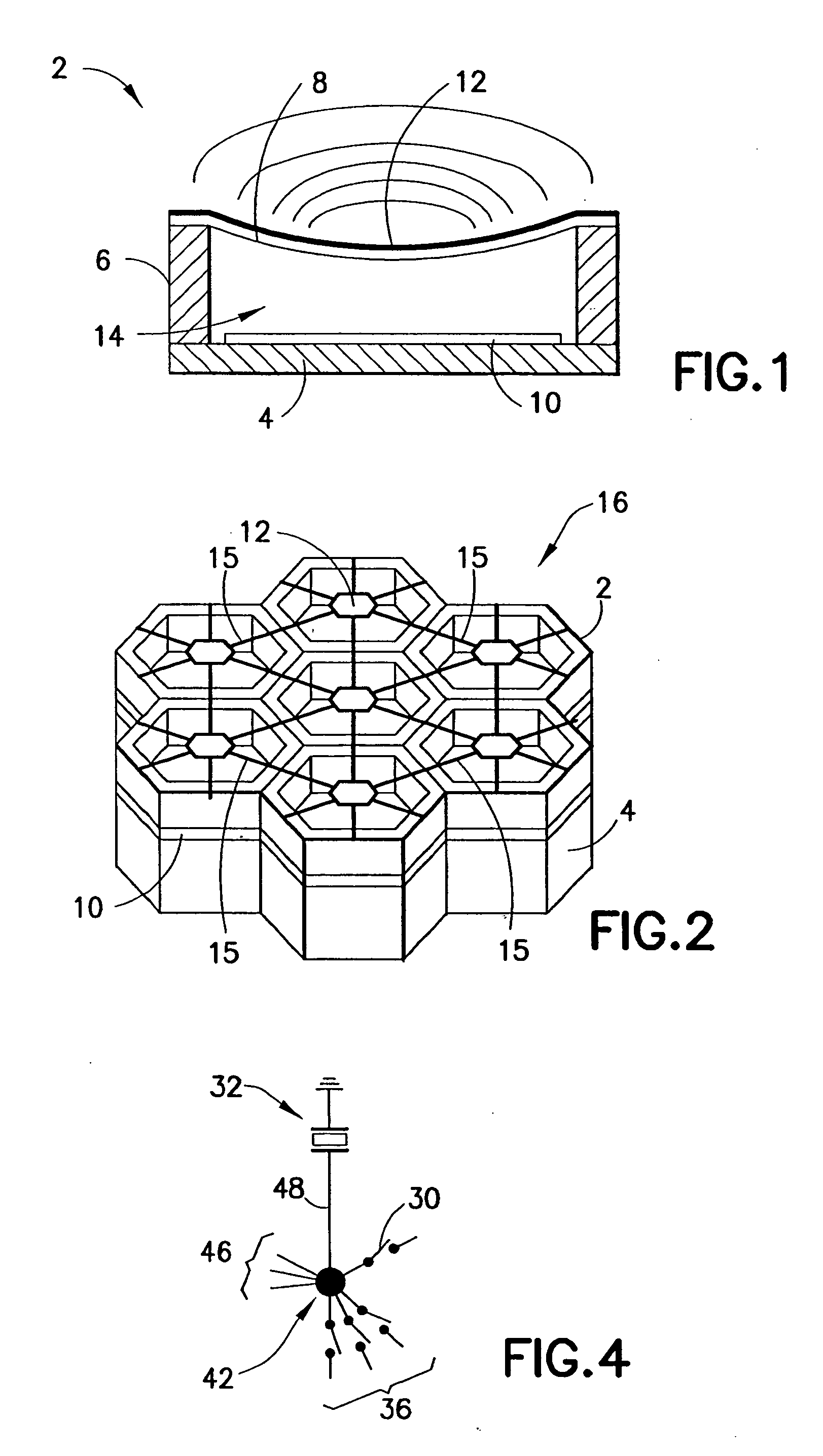
[0054] In accordance with the invention shown in FIG. 11, the top electrode 12 of each individual cMUT cell is connected to the top electrodes of its neighbors by means of electrical connectors that are specially designed to be fuses. More specifically, each of the spokes 15 connecting the vertices of the cell electrode 12 to its neighbors is designed to melt when the current flow therethrough is great enough. In the example depicted in FIG. 11, one top electrode 12′ has been shorted, causing all of its six fuses to be blown. As a result, if a single cell is shorted to ground, that single cell will be electrically isolated from all other cells, as represented by the hatched hexagon 12′ with no spokes in FIG. 11.

[0055]FIGS. 12 and 13 are drawings showing respective top views of two alternative fuse designs for isolating short-circuited sensor cell groups 58 from a bias voltage bus line 50 while minimizing overhead space. FIG. 12 shows serpentine conductors 68 designed to behave as fu...

third embodiment

[0057] In accordance with the invention shown in FIG. 15, each fuse 74 traverses an inactive, but evacuated cMUT cell 76. [However, the inactive and evacuated region that the fuse traverses need not be in the shape of a cell. It could be any other shape.] During the manufacturing process, a layer of silicon oxide (or silicon nitride) is deposited on a silicon substrate. This silicon oxide layer is etched to form cavities for both the active cMUT cells 2 and the inactive cMUT cells 76. The region 78 in FIG. 15 represents a portion of the layer of silicon oxide where cavities are not formed. A layer of silicon nitride (or silicon) is then suspended over the cavities to form the membranes for the cMUT cells. The cavities are then evacuated. The vacuum underneath the inactive cMUT cells 76 improves the thermal isolation of the fuses 74 from the silicon substrate, increasing the likelihood that each fuse 74 will form an open circuit at the specified current rating. Thermal isolation of t...


PUM


Abstract

A device comprising an array of sensors and a multiplicity of bus lines, each sensor being electrically connected to a respective bus line and comprising a respective multiplicity of groups of micromachined sensor cells, the sensor cell groups of a particular sensor being electrically coupled to each other via the bus line to which that sensor is connected, each sensor cell group comprising a respective multiplicity of micromachined sensor cells that are electrically interconnected to each other and not switchably disconnectable from each other, the device further comprising means for isolating any one of the sensor cell groups from its associated bus line and in response to any one of the micromachined sensor cells of that sensor cell group being short-circuited to ground. In one implementation, the isolating means comprise a multiplicity of fuses. In another implementation, the isolating means comprise a multiplicity of short circuit protection modules, each module comprising a current sensor circuit and an electrical isolation switch.

Description

BACKGROUND OF THE INVENTION [0001] This invention generally relates to arrays of sensors that operate electronically. In particular, the invention relates to micromachined ultrasonic transducer (MUT) arrays. One specific application for MUTs is in medical diagnostic ultrasound imaging systems. Another specific example is for non-destructive evaluation of materials, such as castings, forgings, or pipelines, using ultrasound. [0002] The quality or resolution of an ultrasound image is partly a function of the number of transducers that respectively constitute the transmit and receive apertures of the transducer array. Accordingly, to achieve high image quality, a large number of transducers is desirable for both two- and three-dimensional imaging applications. The ultrasound transducers are typically located in a hand-held transducer probe that is connected by a flexible cable to an electronics unit that processes the transducer signals and generates ultrasound images. The transducer p...

Claims


Application Information

Patent Timeline
Patent Type & Authority Applications(United States)
IPC IPC(8): H01J40/14G01J1/42H03F3/08
CPCH04R23/00B06B1/0292
Inventor LEE, WARRENMILLS, DAVID MARTINCLAYDON, GLENN SCOTTRIGBY, KENNETH WAYNETIAN, WEI-CHENGLI, YE-MINGSUN, JIESMITH, LOWELL SCOTTCHU, STANLEY CHIENWUWONG, SAM YIE-SUMKWON, HYON-JIN
Owner GENERAL ELECTRIC CO
Why Eureka
Try Eureka