Light emitting diode with a quasi-omnidirectional reflector

a light-emitting diode and quasi-omnidirectional technology, applied in the direction of basic electric elements, electrical appliances, semiconductor devices, etc., can solve the problems of loss of ultraviolet light, partial to high color temperature, and difficult control of the color of the light sour

Inactive Publication Date: 2006-07-06
IND TECH RES INST
View PDF11 Cites 114 Cited by
  • Summary
  • Abstract
  • Description
  • Claims
  • Application Information

AI Technical Summary

Benefits of technology

[0012] According the reasons above, one objective of the invention is to provide a light emitting diode (LED) having a quasi-omnidirectional reflector, which uses a method of optical film coating to manufacture a wi

Problems solved by technology

However, because most of the light spectrum produced by this LED that combines the blue light LED 10 and the yellow luminescent material 20 are the blue lights, the color temperature is partial to high and the color of the light source is not very easy to control.
However, it causes a loss of the UV

Method used


Image

  • Light emitting diode with a quasi-omnidirectional reflector
  • Light emitting diode with a quasi-omnidirectional reflector
  • Light emitting diode with a quasi-omnidirectional reflector

Examples


first embodiment

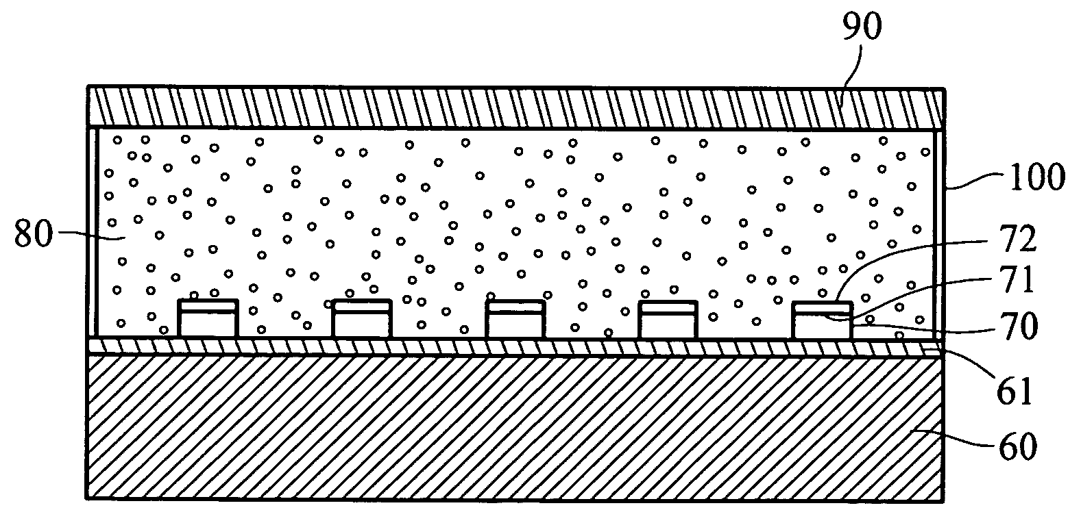
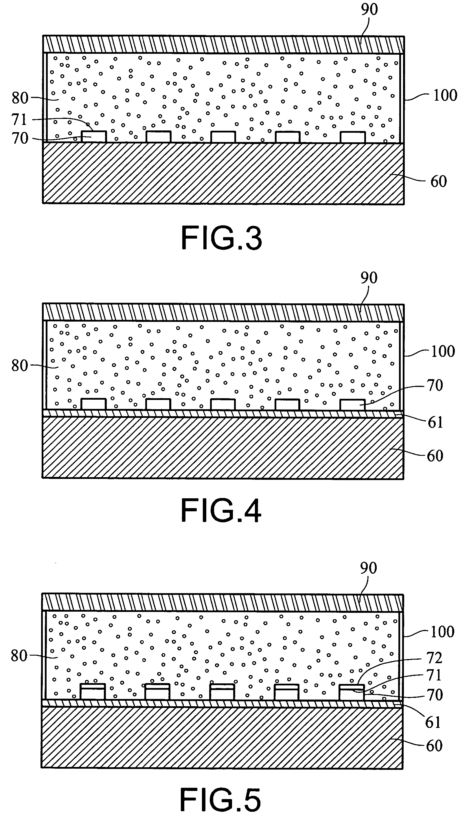
[0027] Please refer to FIG. 3, it is a diagram of a LED with a quasi-omnidirectional reflector according to the invention. This LED includes: a substrate 60; at least one LED chips 70, a luminescent gel 80, a wild angle cut-off filter 90 and a side reflector 100.

[0028] The LED chip 70 is disposed on a substrate 60 which has an ability for providing a circuit thereon and for driving the LED chip 70 to emit a light by an external current. A light emits from an emitting surface of the LED chip 70 for providing a light source to excite the luminescent gel 80.

[0029] In the drawing, this LED includes five LED chips. However, practically a user can dispose one or more LED chips therein to provide the desirable brightness. When more than one LED chips 70 are disposed therein, they can be arranged in matrix.

[0030] The LED chip 70 can be a UV light LED chip. The LED chip 70 can be disposed on the substrate by forming a circuit on the substrate first and then connecting the LED chip 70 to th...

second embodiment

[0048] A UV light LED and a blue light LED are used respectively in the structure of the second embodiment for two sets of experiments according to the invention. A light spectrum above the wild angle cut-off filter 90 is measured for showing the reflection effect of the wild angle cut-off filter to a UV light or a blue light, and for showing the transmission effect of the wild angle cut-off filter to a visible light.

[0049] This LED uses a 382 nm UV light LED to perform the excitation and co-works it with a red / green / blue luminescent material which is able to be excited by the above UV light, and uses a luminescent gel 80 composing of a polymer gel which is able to penetrate a UV light.

[0050] Because a light from the LED chip 70 penetrating from the luminescent gel 80 goes through the wild angle cut-off filter 90 and then goes into the air, if the refractive index of the luminescent gel is 1.48, and the incident angle of the light is larger than 42.5 degree, the light will be total...


PUM


Abstract

A light emitting diode with a quasi-omnidirectional reflector comprises a luminescent gel which is coated surrounding a UV light LED chip and a quasi-omnidirectional reflector which is disposed above the luminescent gel. The quasi-omnidirectional reflector is a wild angle cut-off filter which is made by a cooperation of a method for an optical film coating and a property of a total reflection. According to the property of the optical film coating, a light with an incident angle smaller than a critical angle can be reflected, such that a light form the LED chip is confined in the luminescent gel, which makes the luminescent material is excited as much as possible for improving the conversion efficiency of the light. When this LED chip co-works with different colors of the luminescent gels, different colors of lights are excited and produced.

Description

BACKGROUND [0001] 1. Field of Invention [0002] The invention relates to a light emitting diode (LED) which applies to a luminescence device, and in particular to a light emitting diode which has a quasi-omnidirectional reflector. [0003] 2. Related Art [0004] So called “White Light” usually means a light mixing multiple colors of lights. A white light that human can see includes at least two mixed wavelengths of the color lights. For example, a blue light combines with a yellow light producing a two wavelength white light; and a blue light, a green light and a red light mix together producing a three wavelength white light. [0005] White light LED (light emitting diode) has two major types according to the filler inside: One is organic LED and the other is inorganic LED. At present, there are three major white light sources by semiconductors: first, using a blue, a red and a green light LED chips to compose a white light luminescence module, which has advantages of high light emitting...

Claims


Application Information

Patent Timeline
IPC IPC(8): H01L33/00H01L33/44H01L33/50H01L33/56H01L33/58H01L33/60
CPCH01L33/44H01L33/50H01L33/58H01L33/60
Inventor SU, JUNG-CHIEHCHU, CHENG-WEI
Owner IND TECH RES INST
Why Eureka
Try Eureka