Method for manufacturing ink-jet printhead

a technology of inkjet printing and printhead, which is applied in the field of inkjet printing head, can solve the problems of degrading to an ejection property, becoming more difficult to process the substrate, and virtually impossible to process the substrate having such a thickness using existing semiconductor processes, so as to improve the linearity of ink droplets, improve the ejection performance, and improve the effect of structur

Inactive Publication Date: 2006-07-06
HEWLETT PACKARD DEV CO LP
View PDF6 Cites 17 Cited by
  • Summary
  • Abstract
  • Description
  • Claims
  • Application Information

AI Technical Summary

Benefits of technology

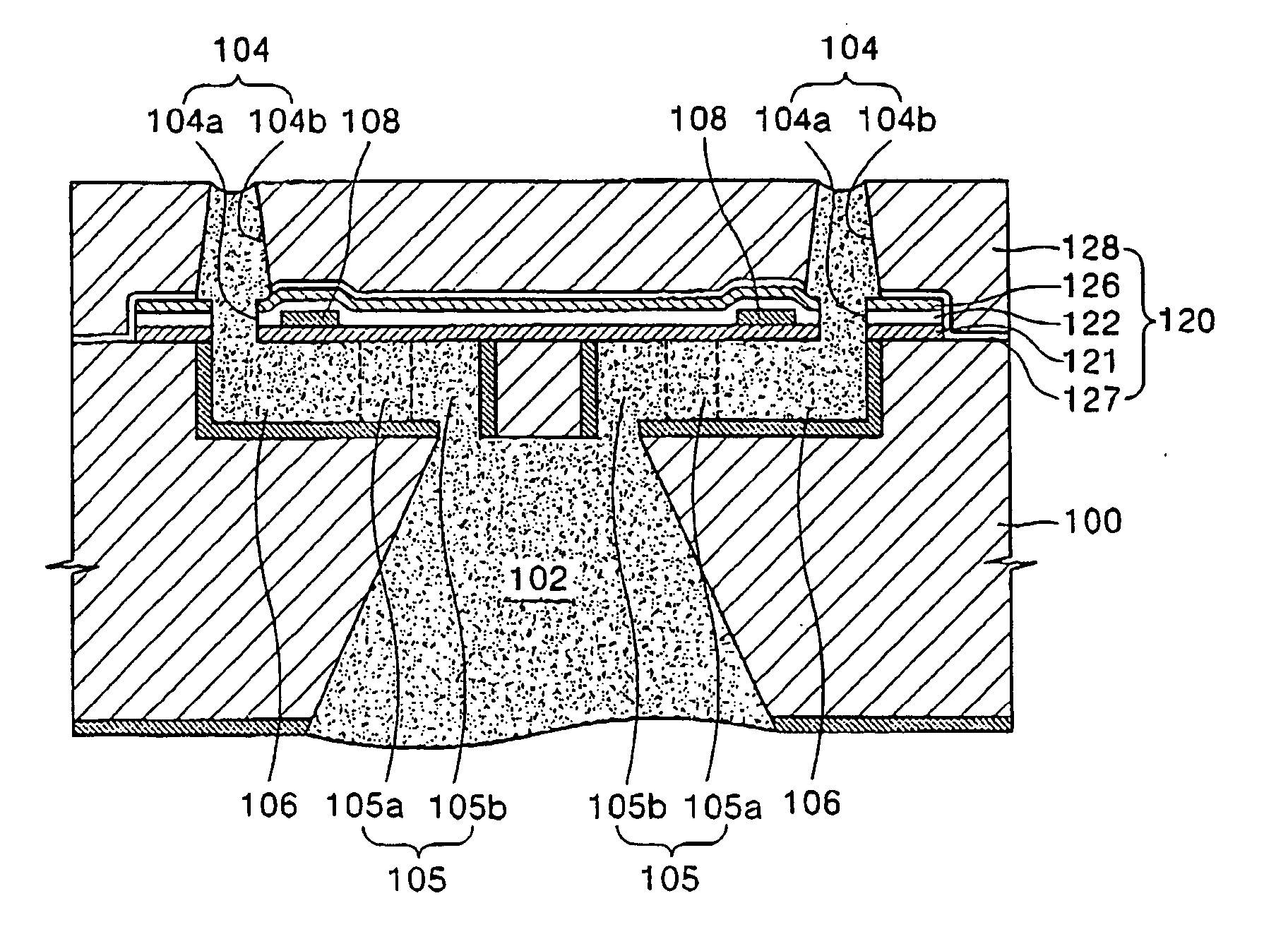
[0021] The present invention is therefore directed to an ink-jet printhead having an improved structure in which an ink passage is formed in a same plane as an ink chamber to improve ejection performance, a metallic nozzle plate is disposed on a substrate to improve linearity of ink droplets ejected through a nozzle, and heat generated by a heater is effectively dissipated to increase a driving frequency of the printhead, and a method for manufacturing the same, which substantially overcome one or more of the problems due to the limitations and disadvantages of the related art.
[0029] It is therefore another feature of an embodiment of the present invention to provide a method for manufacturing an ink-jet printhead including forming a sacrificial layer having a predetermined depth on a front surface of a substrate; sequentially stacking a plurality of passivation layers on the front surface of the substrate, on which the sacrificial layer is formed, and forming a heater and a conductor connected to the heater between adjacent passivation layers; forming a heat dissipating layer of metal on the plurality of passivation layers and forming a nozzle, through which ink is ejected, through the heat dissipating layer and the plurality of passivation layers to expose the sacrificial layer; forming a manifold for supplying ink on a rear surface of the substrate; removing the sacrificial layer to form an ink chamber and an ink passage; and providing flow communication between the manifold and the ink passage.

Problems solved by technology

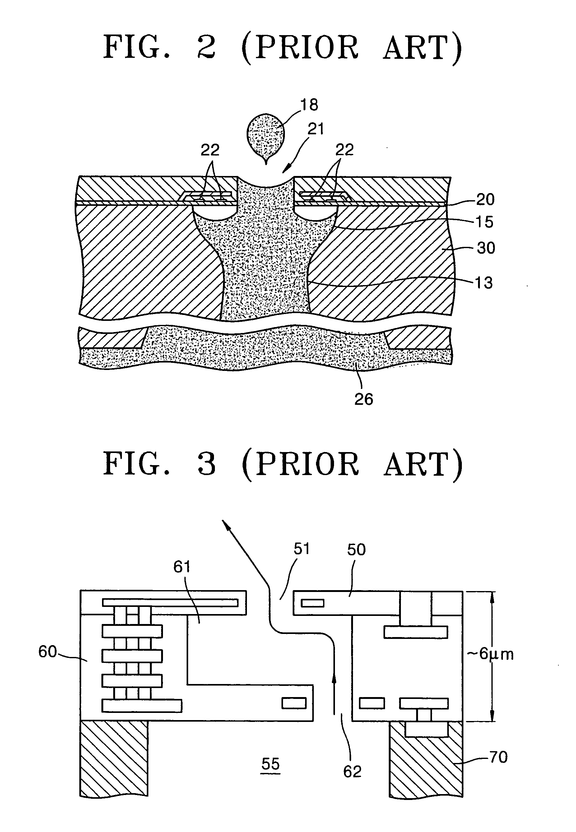
Accordingly, pressure generated by bubbles for ejecting ink is dispersed by the ink, resulting in degradation to an ejection property.
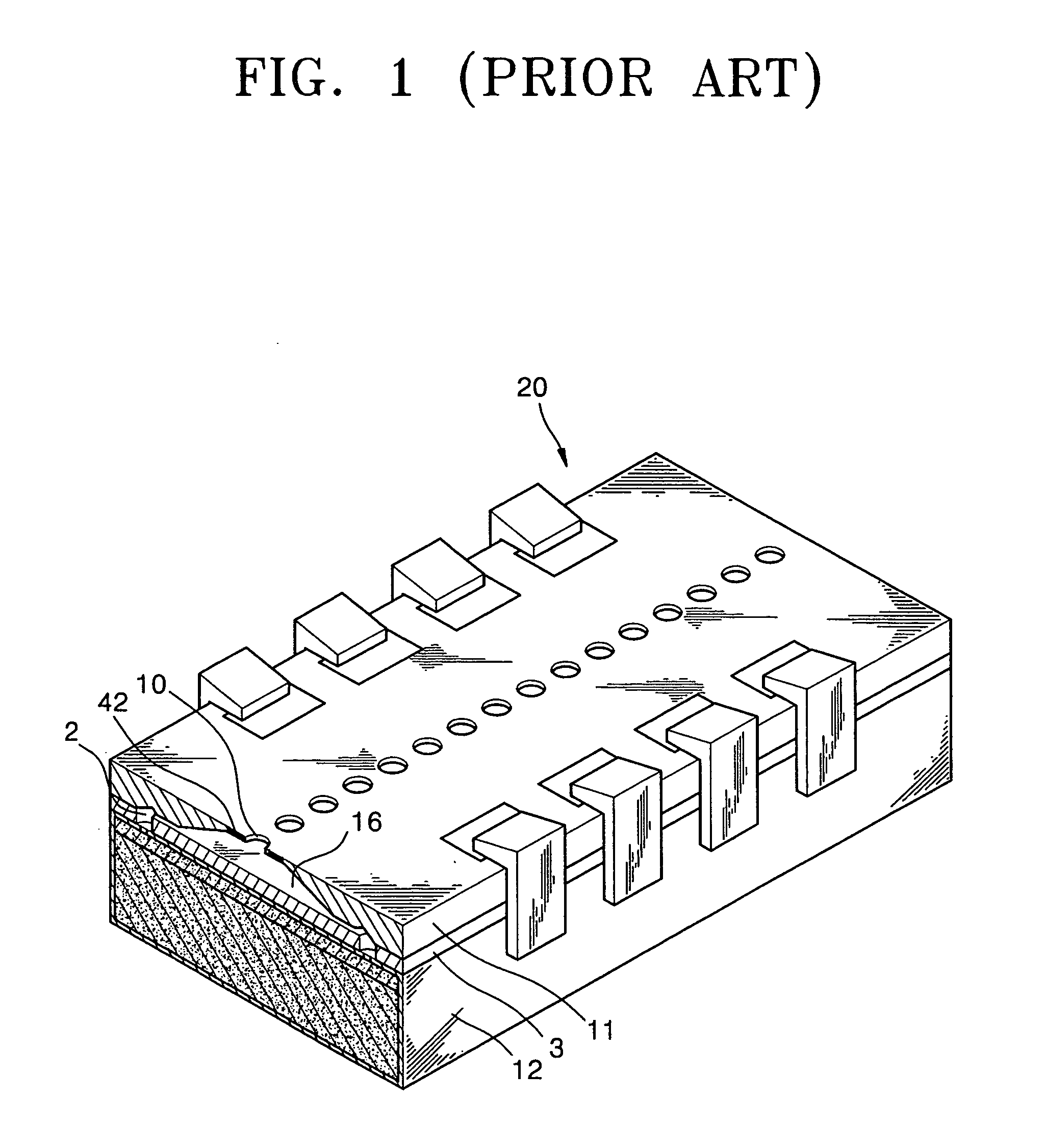
When a thin substrate is used to reduce the size of the ink chamber 16, it becomes more difficult to process the substrate 11.
It is virtually impossible, however, to process a silicon substrate having such a thickness using existing semiconductor processes.
Thus, a process of manufacturing such an ink-jet printhead becomes complicated, and an ink passage, which significantly affects an ejection property, cannot be very elaborate.
Thus, it is difficult to form an ink chamber having an optimum shape.

Method used


Image

  • Method for manufacturing ink-jet printhead
  • Method for manufacturing ink-jet printhead
  • Method for manufacturing ink-jet printhead

Examples


Embodiment Construction

[0049] Korean Patent Application No. 2003-33840, filed on May 27, 2003, in the Korean Intellectual Property Office, and entitled: “Ink-Jet Printhead and Method for Manufacturing the Same,” is incorporated by reference herein in its entirety.

[0050] The present invention will now be described more fully hereinafter with reference to the accompanying drawings, in which exemplary embodiments of the invention are shown. The invention may, however, be embodied in different forms and should not be construed as limited to the embodiments set forth herein. Rather, these embodiments are provided so that this disclosure will be thorough and complete, and will fully convey the scope of the invention to those skilled in the art. In the figures, the dimensions of layers and regions are exaggerated for clarity of illustration. It will also be understood that when a layer is referred to as being “on” another layer or substrate, it can be directly on the other layer or substrate, or intervening lay...


PUM

PropertyMeasurementUnit
thicknessaaaaaaaaaa
depthaaaaaaaaaa
thicknessaaaaaaaaaa

Abstract

In an ink-jet printhead and a method for manufacturing the same, the ink-jet printhead includes a substrate, an ink chamber to be filled with ink formed on a front surface of the substrate, a manifold for supplying ink to the ink chamber formed on a rear surface of the substrate, and an ink passage in flow communication with the ink chamber and the manifold formed parallel to the front surface of the substrate; a nozzle plate including a plurality of passivation layers formed of an insulating material on the front surface of the substrate, a heat dissipating layer formed of a metallic material, and a nozzle in flow communication with the ink chamber; and a heater and a conductor, the heater being positioned on the ink chamber and heating ink in the ink chamber, and the conductor for applying a current to the heater.

Description

CROSS REFERENCE TO RELATED APPLICATION(S) [0001] This is a divisional application based on pending application Ser. No. 10 / 853,643, filed May 26, 2004, which in turn is a continuation-in-part of application Ser. No. 10 / 691,588, filed Oct. 24, 2003, now U.S. Pat. No. 6,979,076 B2, the entire contents of both of which are hereby incorporated by reference.BACKGROUND OF THE INVENTION [0002] 1. Field of the Invention [0003] The present invention relates to an ink-jet printhead and a method for manufacturing the same. More particularly, the present invention relates to an ink-jet printhead, in which an ink passage is formed in a same plane as an ink chamber to improve ejection performance, a metallic nozzle plate is disposed on a substrate to improve linearity of ink droplets ejected through a nozzle, and heat generated by a heater is effectively dissipated to increase a driving frequency of the printhead, and a method for manufacturing the same. [0004] 2. Description of the Related Art [...

Claims


Application Information

Patent Timeline
Patent Type & Authority Applications(United States)
IPC IPC(8): B41J2/175B41J2/16
CPCB41J2/1412B41J2/14129B41J2/14137B41J2/1601B41J2/1603B41J2/1626B41J2/1628B41J2/1629B41J2/1631B41J2/1632B41J2/1639B41J2/1642B41J2/1643B41J2/1646B41J2002/1437B41J2002/14387
Inventor KIM, MIN-SOOSHIN, SU-HOOH, YONG-SOOLIM, HYUNG-TAEKSHIN, JONG-WOOBAEK, SEOG-SOON
Owner HEWLETT PACKARD DEV CO LP
Why Eureka
Try Eureka