Micro-actuator, vibration canceller, head gimbal assembly, and disk drive unit with the same

a micro-actuator and vibration cancelling technology, applied in the direction of magnetic recording, data recording, instruments, etc., can solve the problems of affecting the dynamic performance of the hga, adversely affecting the ability of the read/write head to accurately read data, and becoming more and more difficult to quickly and accurately position the read/write, so as to improve the resonance characteristics and fine head position adjustments

Inactive Publication Date: 2006-07-06
SAE MAGNETICS (HK) LTD
View PDF28 Cites 53 Cited by
  • Summary
  • Abstract
  • Description
  • Claims
  • Application Information

AI Technical Summary

Benefits of technology

[0015] A main feature of the present invention is to provide an improved micro-actuator and head gimbal assembly that enables fine head position adjustments and provides improved resonance characteristics.
[0016] Another feature of the present invention is to provide a vibration canceling system for micro-actuators that can be easily and effectively incorporated into a head gimbal assembly.
[0017] Another feature of the present invention is to provide an improved disk drive unit with a large servo bandwidth and storage capacity, as well as fine head position adjustment using a micro-actuator.
[0021] A disk drive unit in accordance with another embodiment of the present invention comprises a head gimbal assembly, a drive arm to connect with the head gimbal assembly, a disk, and a spindle motor to spin the disk. The head gimbal assembly includes a slider, a micro-actuator with a vibration cancellation system, preferably incorporating at least one PZT element, and a suspension to load the slider and the micro-actuator. The micro-actuator adjusts the position of the slider, and the at least one PZT element of the vibration cancellation system is operable to cancel at least some of the suspension vibration resulting from operation of the micro-actuator.
[0022] In accordance with the invention, the vibration cancellation system can have a variety of configurations, each of which is capable of at least partially canceling the suspension vibration that results from movement of the slider by operation of the micro-actuator. The slider is connected with the actuate arms of the micro-actuator, and the base-part plate of the micro-actuator is mounted on the suspension. Thus, when the micro-actuator is excited, the actuate arms will bend thereby causing the slider to displace in a controlled manner in order to make a fine head position adjustment. At the same time, the vibration cancellation system operates to cancel the suspension resonance resulting from operation of the micro-actuator. As a result, the resonance characteristic of the suspension is improved, which enables a larger servo bandwidth and improved capacity for disk drive devices.

Problems solved by technology

As track density increases, it becomes more and more difficult using known technology to quickly and accurately position the read / write head over the desired information tracks on the storage media.
However, because of the inherent tolerances of the VCM and the head suspension assembly, the slider 203 cannot achieve quick and fine position control which adversely impacts the ability of the read / write head to accurately read data from and write data to the disk.
The reaction force causes a suspension resonance, or vibration, that will negatively impact the dynamic performance of the HGA.
While the PZT micro-actuator described above provides an effective and reliable solution for fine tuning the position of the slider, it also results in certain disadvantages.
This suspension vibration resonance corresponds to the resonance of the excited suspension base plate, thereby resulting in a significant vibration that limits the servo bandwidth and the capacity improvement of the disk drive device.

Method used


Image

  • Micro-actuator, vibration canceller, head gimbal assembly, and disk drive unit with the same
  • Micro-actuator, vibration canceller, head gimbal assembly, and disk drive unit with the same
  • Micro-actuator, vibration canceller, head gimbal assembly, and disk drive unit with the same

Examples


first embodiment

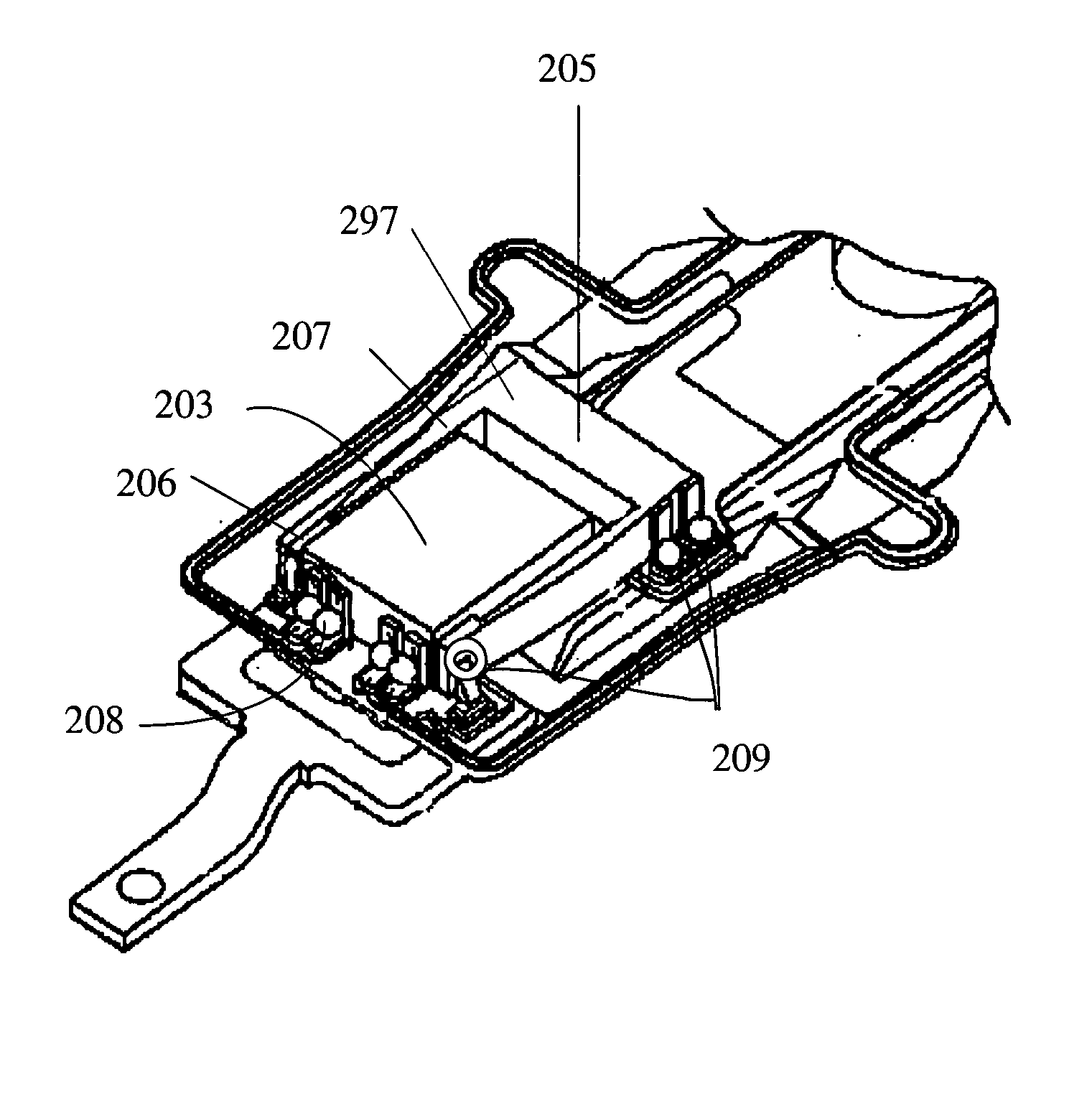
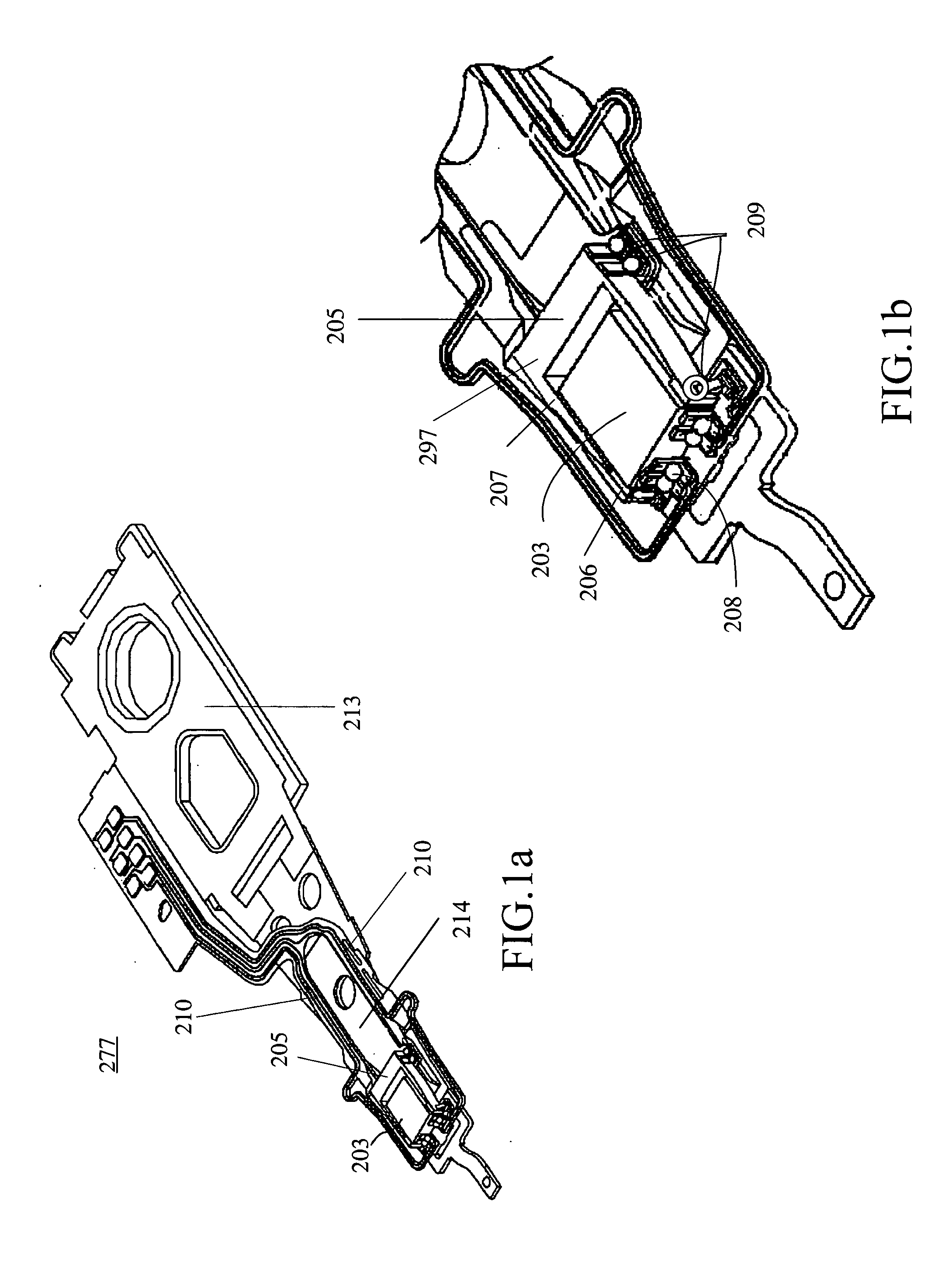
[0050]FIG. 3a shows a head gimbal assembly (HGA) 3 incorporating a first exemplary embodiment of the vibration canceling system of the present invention. This first embodiment is shown in FIGS. 3a and 3b as being implemented in a conventional HGA of the type shown in FIGS. 1a and 1b. As explained above, this type of conventional HGA includes a slider 31, a micro-actuator 32 and a suspension 8 to load the slider 31 and the micro-actuator 32. The suspension 8 includes a load beam 17, a flexure 13, a hinge 15 and a base plate 11. The load beam 17 has a dimple 329 (see FIG. 5) formed thereon. On the flexure 13, a plurality of connection pads 308 are provided to connect with a control system (not shown) at one end and a plurality of electrical multi-traces 309, 311 are provided at the other end. The HGA is configured for connection via base plate11 with a drive arm of a disk drive device. A voice-coil motor (VCM) is provided in the disk drive device for controllably driving the drive arm...

fifth embodiment

[0064]FIGS. 11a and 11b show the invention in which the canceling arms 325a and 325b of the micro-actuator are coupled at their top end with a support plate 1102 or 1103. The support plate 1102 of FIG. 11a is connected with the canceling arms 325a and 325b in a vertical orientation. In contrast, the support plate 1103 in FIG. 11b is connected with the canceling arms 325a and 325b in a horizontal orientation. In addition, the two actuate arms 322a and 322b may be coupled together with another support plate (not shown) that is similar to the support plate 1102 or 1103. The use of the support plates to couple the arms of the micro-actuator helps to further reduce vibration in the device.

[0065]FIGS. 11c and 11d show a sixth embodiment of the invention in which the vibration canceling arms 1002 and 1004 are coupled at the ends thereof with a support plate 1107 or 1108. Other than the support plates 1107 and 1108, the sixth embodiment is similar to the embodiment of FIGS. 10a-10c. Like th...


PUM

PropertyMeasurementUnit
frequencyaaaaaaaaaa
densityaaaaaaaaaa
track densityaaaaaaaaaa

Abstract

A head gimbal assembly (HGA) for a disk drive unit that includes a micro-actuator, a slider and a suspension to load the slider and the micro-actuator. The micro-actuator is provided with a vibration canceller that counteracts forces generated by activation of the micro-actuator when making fine head position adjustments. The vibration canceller incorporates PZT elements that generate counteracting forces in the bottom plate of the micro-actuator to cancel the vibration generated by the micro-actuator, thereby providing improved resonance performance for a disk drive unit.

Description

FIELD OF THE INVENTION [0001] The present invention relates to disk drive units and, more particularly, to a micro-actuator, a vibration canceller and a head gimbal assembly (HGA) incorporating piezoelectric (PZT) elements. More specifically, the present invention is directed to an improved PZT micro-actuator for an HGA that includes a vibration canceling system that cancels suspension vibration generated by excitation of the micro-actuator when fine tuning the position of a read / write head. BACKGROUND OF THE INVENTION [0002] One known type of information storage device is a disk drive device that uses magnetic media to store data and a movable read / write head that is positioned over the media to selectively read from or write to the disk. [0003] Consumers are constantly desiring greater storage capacity for such disk drive devices, as well as faster and more accurate reading and writing operations. Thus, disk drive manufacturers have continued to develop higher capacity disk drives...

Claims


Application Information

Patent Timeline
Patent Type & Authority Applications(United States)
IPC IPC(8): G11B5/56
CPCG11B5/4826G11B5/4873G11B5/5552
Inventor YAO, MINGGAOSHIRAISHI, MASASHI
Owner SAE MAGNETICS (HK) LTD
Why Eureka
Try Eureka