
White-light emitting device and the use thereof

a technology of white light and white light, which is applied in the field of white light emitting devices, can solve the problems of inferior cri (color rendering index), cold cathode fluorescent lamps, poisonous mercury, etc., and achieve the effect of superior cri and reducing the thickness of backlight modules

Inactive Publication Date: 2006-07-06
GENESIS PHOTONICS
View PDF4 Cites 29 Cited by
  • Summary
  • Abstract
  • Description
  • Claims
  • Application Information

AI Technical Summary

Benefits of technology

[0009] Therefore, it is an object of the present invention to provide a white-light emitting device which has a superior CRI, and which is applicable to a backlight module so as to reduce the thickness of the backlight module.

Problems solved by technology

However, the cold cathode fluorescent lamp has disadvantages, such as use of poisonous mercury, fragility, inferior CRI (color rendering index), etc.

Method used


Image

  • White-light emitting device and the use thereof
  • White-light emitting device and the use thereof
  • White-light emitting device and the use thereof

Examples


Embodiment Construction

[0029] Before the present invention is described in greater detail, it should be noted that like elements are denoted by the same reference numerals throughout the disclosure.

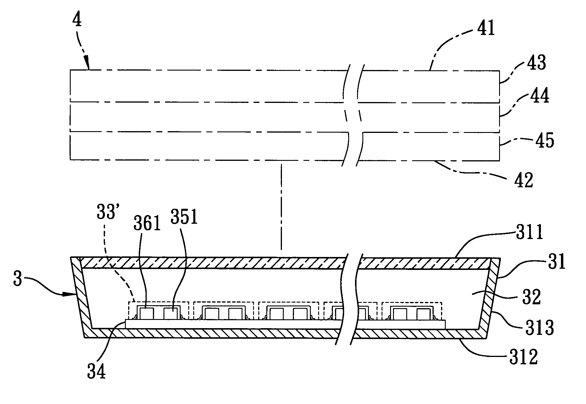
[0030] Referring to FIGS. 3, 4 and 5, the first preferred embodiment of a white-light emitting device 33′ according to this invention is shown to be installed in a direct type backlight module 3. The backlight module 3 is mounted below a liquid crystal module 4. The liquid crystal module 4 has a front side 41 and a rear side 42, and includes a color filter unit 43, a liquid crystal unit 44, and a glass substrate unit 45 along a direction from the front side 41 to the rear side 42. The backlight module 3 includes a housing 31 defining a receiving space 32, and a plurality of the white-light emitting device 33′ mounted in the receiving space 32. The housing 31 is configured as a wedge shape, and has a top wall 311 proximate to the rear side 42 of the liquid crystal module 4, a bottom wall 312 opposite to the top...


PUM


Abstract

A white-light emitting device includes a first die and a second die. The first die has a first semiconductor light-emitting layer emitting a first primary color light. The second die has a second semiconductor light-emitting layer emitting a second primary color light, and a third semiconductor light-emitting layer mounted proximate to the second semiconductor light-emitting layer and emitting a third primary color light. The first primary color light is combined with the second and third primary color lights so as to produce white light.

Description

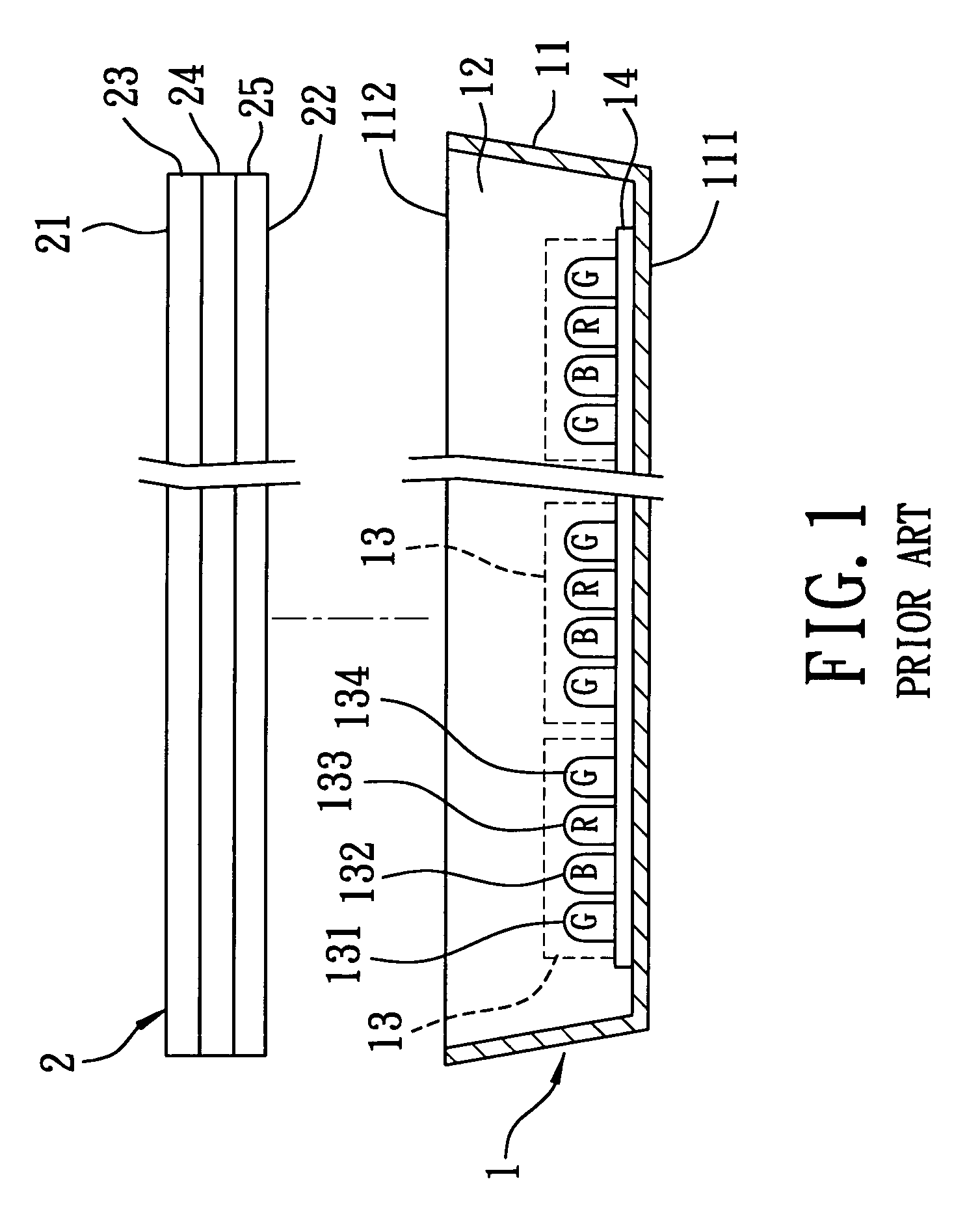
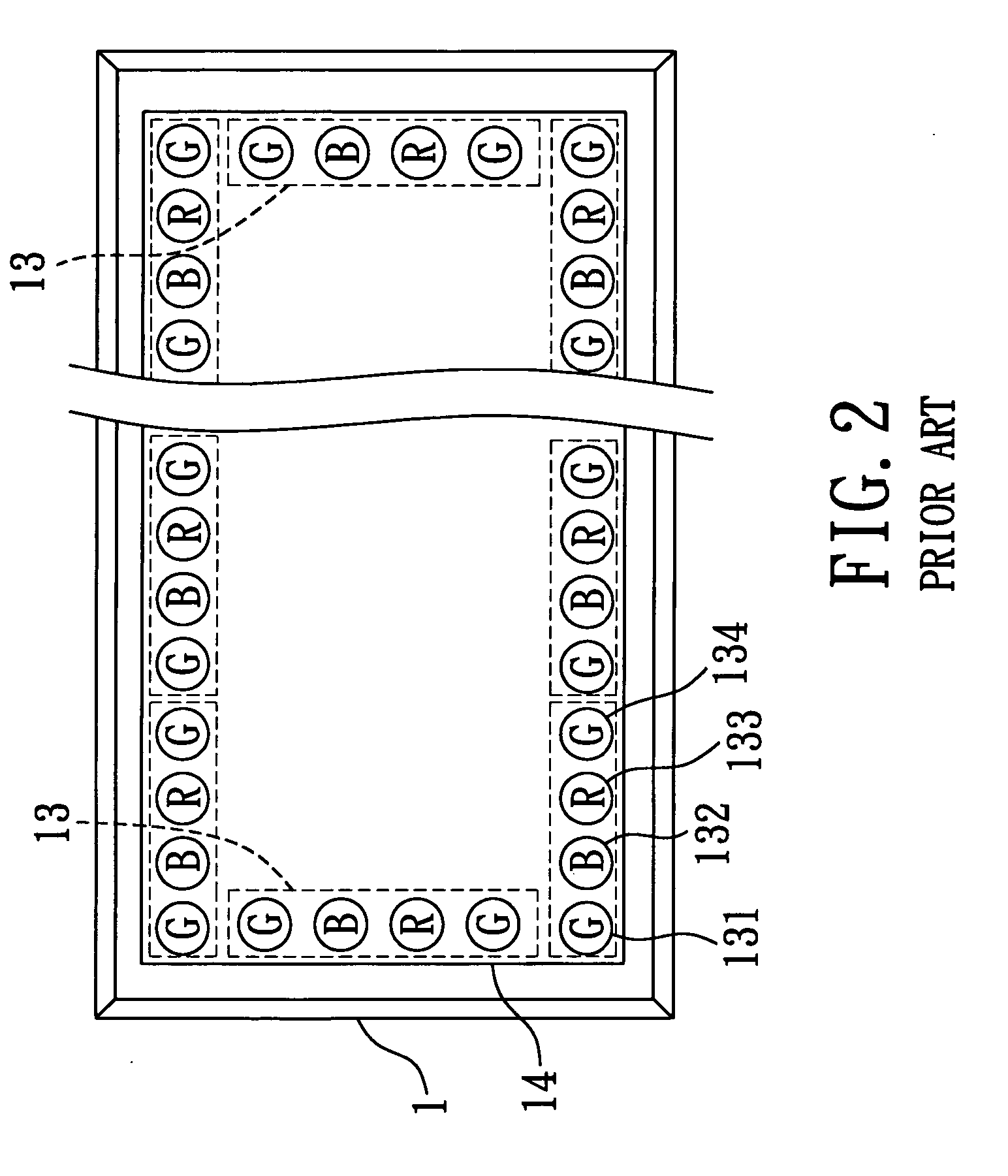
CROSS-REFERENCE TO RELATED APPLICATION [0001] This application claims priority of Taiwanese Application No. 094100340, filed on Jan. 6, 2005, and Taiwanese Application No. 094106030, filed on Mar. 1, 2005. BACKGROUND OF THE INVENTION [0002] 1. Field of the Invention [0003] The invention relates to a white-light emitting device, more particularly to a white-light emitting device applicable to a backlight module. [0004] 2. Description of the Related Art [0005] There are usually two types of backlight modules suitable for use in a liquid crystal display, i.e., a direct type backlight module and a side-edge type backlight module. Conventionally, a cold cathode fluorescent lamp is used as a light source for either type of the backlight modules. However, the cold cathode fluorescent lamp has disadvantages, such as use of poisonous mercury, fragility, inferior CRI (color rendering index), etc. [0006] A backlight module that uses a light emitting diode (LED) as the light source was develope...

Claims


Application Information

Patent Timeline
Patent Type & Authority Applications(United States)
IPC IPC(8): F21V13/00H01L33/08H01L33/32H01L33/62
CPCG02F1/133603G02F1/133609H01L25/0753H01L33/08H01L2224/48091H01L2224/48247H01L2224/49107H01L2924/00H01L2224/48257H01L2924/00014
Inventor CHEN, CHENG-CHUAN
Owner GENESIS PHOTONICS
Learn More