Transferable antireflection material for use on optical display

a technology of anti-reflection materials and optical displays, applied in the field of anti-reflection materials, can solve the problems of reducing the surface energy of the coating layer, reducing the interfacial adhesion of the fluoropolymer layer to the other polymer or substrate layer, and defects in ultra-thin coatings. , to achieve the effect of good adhesion, good durability and low refractivity

Inactive Publication Date: 2006-07-06
3M INNOVATIVE PROPERTIES CO
View PDF6 Cites 45 Cited by
  • Summary
  • Abstract
  • Description
  • Claims
  • Application Information

AI Technical Summary

Benefits of technology

[0013] The film is formed prior to application to the substrate and has at least one low refractive index layer and at least one high refractive index layer coupled to a release film....

Problems solved by technology

However, increasing the fluorine content also decreases the surface energy of the coating layers, which in turn reduces the interfacial adhesion of the fluoropolymer layer to the other polymer or sub...

Method used


Image

  • Transferable antireflection material for use on optical display
  • Transferable antireflection material for use on optical display
  • Transferable antireflection material for use on optical display

Examples


example 1

[0101] On 75 um PET (Product name: O-75, Teijin), L-1 described above was coated by Mayer bar #6 and dried in 80° C. oven for 30 seconds and then put in 120° C. oven for 20 seconds to make a low index layer with approximately 90 nm thickness. On the low index layer, H-1 was coated by Mayer bar #8 and dried in 80° C. oven for 30 seconds and then put in 120° C. oven for 20 seconds. The H-1 coated film was UV exposed for 8 seconds from the PET release layer side with a 120 W Fusion lump (D bulb) under nitrogen gas atmosphere to make a high index layer with approximately 130 nm thickness. On the high index layer, HC-1 was coated by Mayer bar #10 and dried in 80° C. oven for 60 seconds. This coated film was UV exposed for 8 seconds from the PET release layer side with a 120 W Fusion lump (D bulb) under N2 atmosphere to make hard coating layer with approximately 5 um thickness. Moreover, on the hard coating layer, Adh-1 was coated by Mayer bar #9 and dried in 80° C. oven for 60 seconds to...

example 2

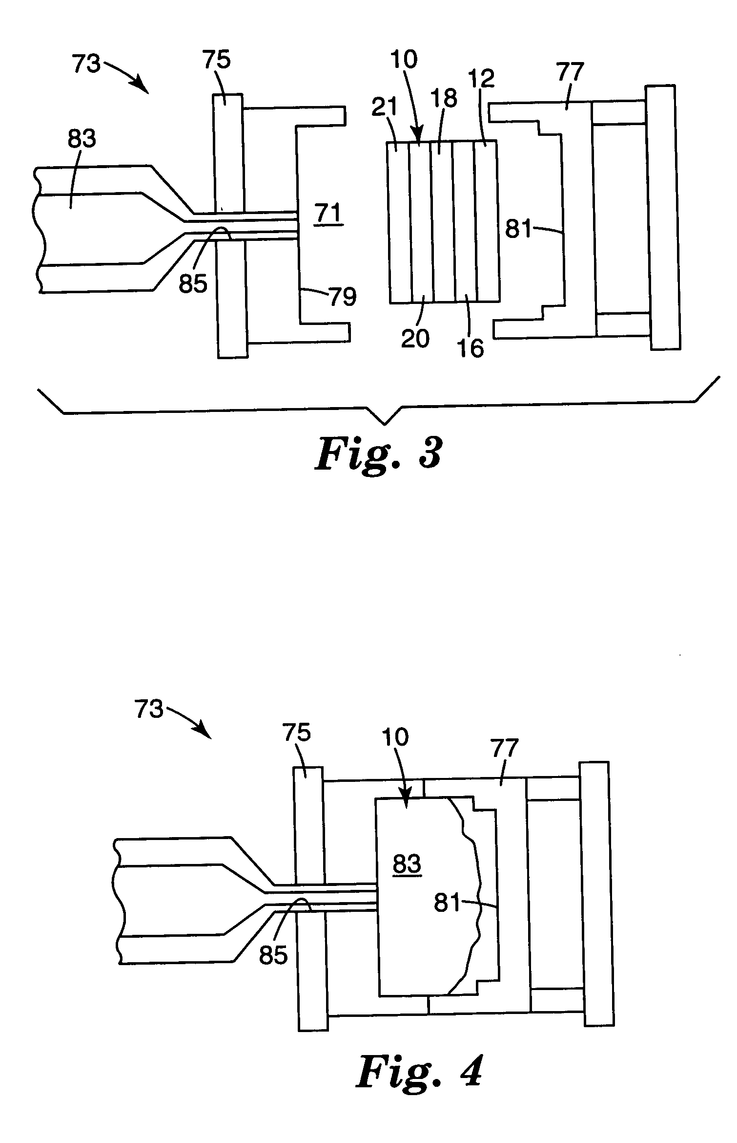
[0103] TAR-1 in Example 1 was inserted into a molding die and PMMA was injection molded with 240° C. injection temperature. The pressed materials were taken out and PET film was removed after cooling. As a result, the anti-reflection layer was successfully transferred on the molding surface.

example 3

[0104] The same procedure was taken to make TAR-2 except using H-3 in Example 1.

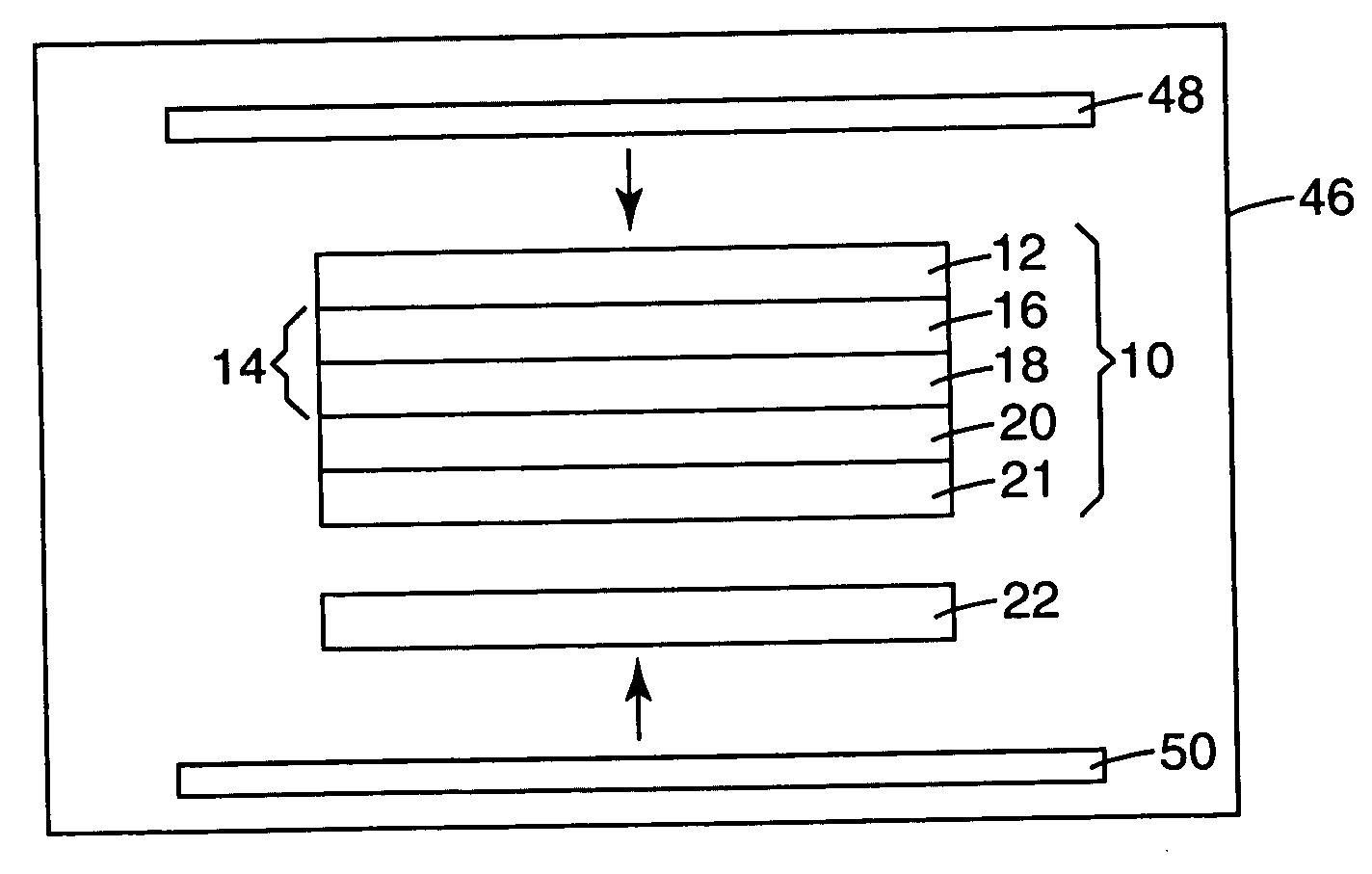
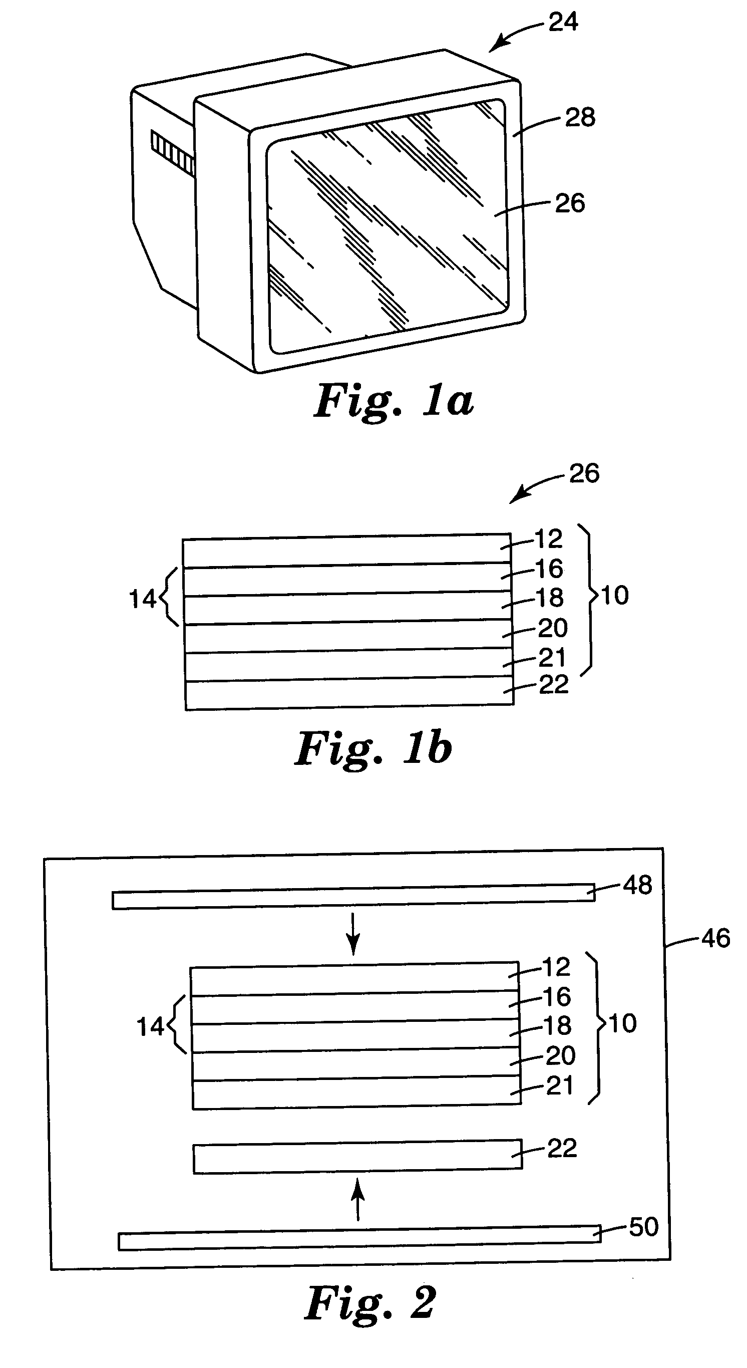
[0105] In the next step, TAR-2 and a commercial acrylic board with 7 cm square and 2 mm thickness were put together and inserted into a heat-press machine with two metal plates and heat-pressed for 40 seconds with 30 MPa pressure. The temperatures of the plates were 180° C. for film / acrylic side and 50° C. for the opposite side. The pressed materials were taken out and PET film was removed after cooling. As a result, the anti-reflection layer was successfully transferred on the acrylic surface.


PUM

PropertyMeasurementUnit
Refractive indexaaaaaaaaaa

Abstract

An optical display, and method for forming an optical display, having improved antireflection properties and durability is formed by applying a transferable antireflection material to an optical substrate through the use of an in-mold or heat press technique or alternatively by an ultraviolet exposure technique. The transferable antireflection material is formed prior to application to the substrate and has at least a low refractive index layer and a high refractive index layer coupled to a release film. The low index reflection layer is preferably a silicone-modified fluoropolymer material having good durability, low refractivity, and appropriate adhesion to the release layer and subsequently applied high index refraction layer. The optical display is then coupled to a housing of an article for use.

Description

TECHNICAL FIELD AND INDUSTRIAL APPLICABILITY OF THE INVENTION [0001] The present invention relates to antireflection materials and more specifically to transferable antireflection materials for optical goods. BACKGROUND OF THE INVENTION [0002] Antireflective polymer films (“AR films”), or AR coatings, are becoming increasingly important in the display industry. New applications are being developed for low reflective films and other AR coatings that are applied to optical substrates of articles used in the computer, television, appliance, mobile phone, aerospace and automotive industries. [0003] AR films are typically constructed by alternating high and low refractive index polymer layers in order to minimize the amount of light that is reflected. Desirable features in AR films for use on the substrate of the articles are the combination of a low percentage of reflected light (e.g. 1.5% or lower) and durability to scratches and abrasions. These features are obtained in AR constructio...

Claims


Application Information

Patent Timeline
IPC IPC(8): B05D5/12B05D5/06
CPCC03C17/30C03C17/3405C03C2217/445C03C2217/475G02B1/111G02F1/133502
Inventor MIZUNO, KAZUHIKO
Owner 3M INNOVATIVE PROPERTIES CO
Why Eureka
Try Eureka