

Nonaqueous electrolyte secondary battery and method for producing same
a technology of nonaqueous electrolyte and secondary batteries, which is applied in the field of nonaqueous electrolyte secondary batteries and a method for manufacturing the same, can solve the problems of deterioration of battery characteristics, and negative electrode conductivity deterioration due to charging/discharging cycle characteristics, and achieve excellent charging/discharging cycle characteristics and the effect of deterioration of the conductivity of the negative electrod
- Summary
- Abstract
- Description
- Claims
- Application Information
AI Technical Summary
Benefits of technology
Problems solved by technology
Method used
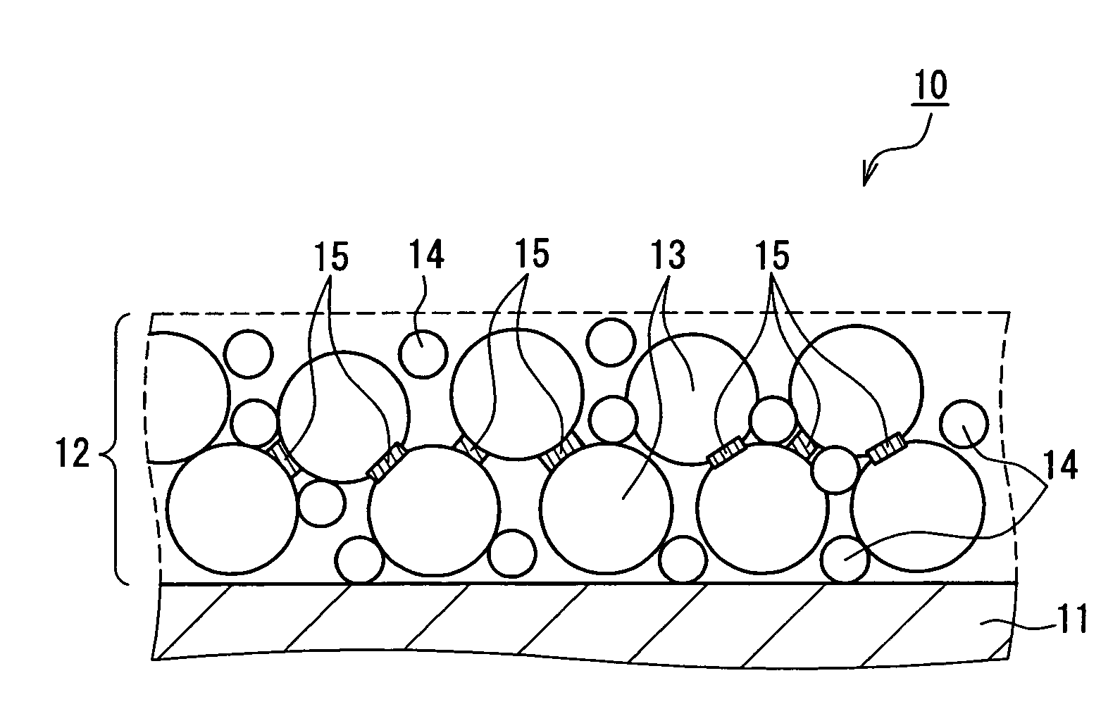
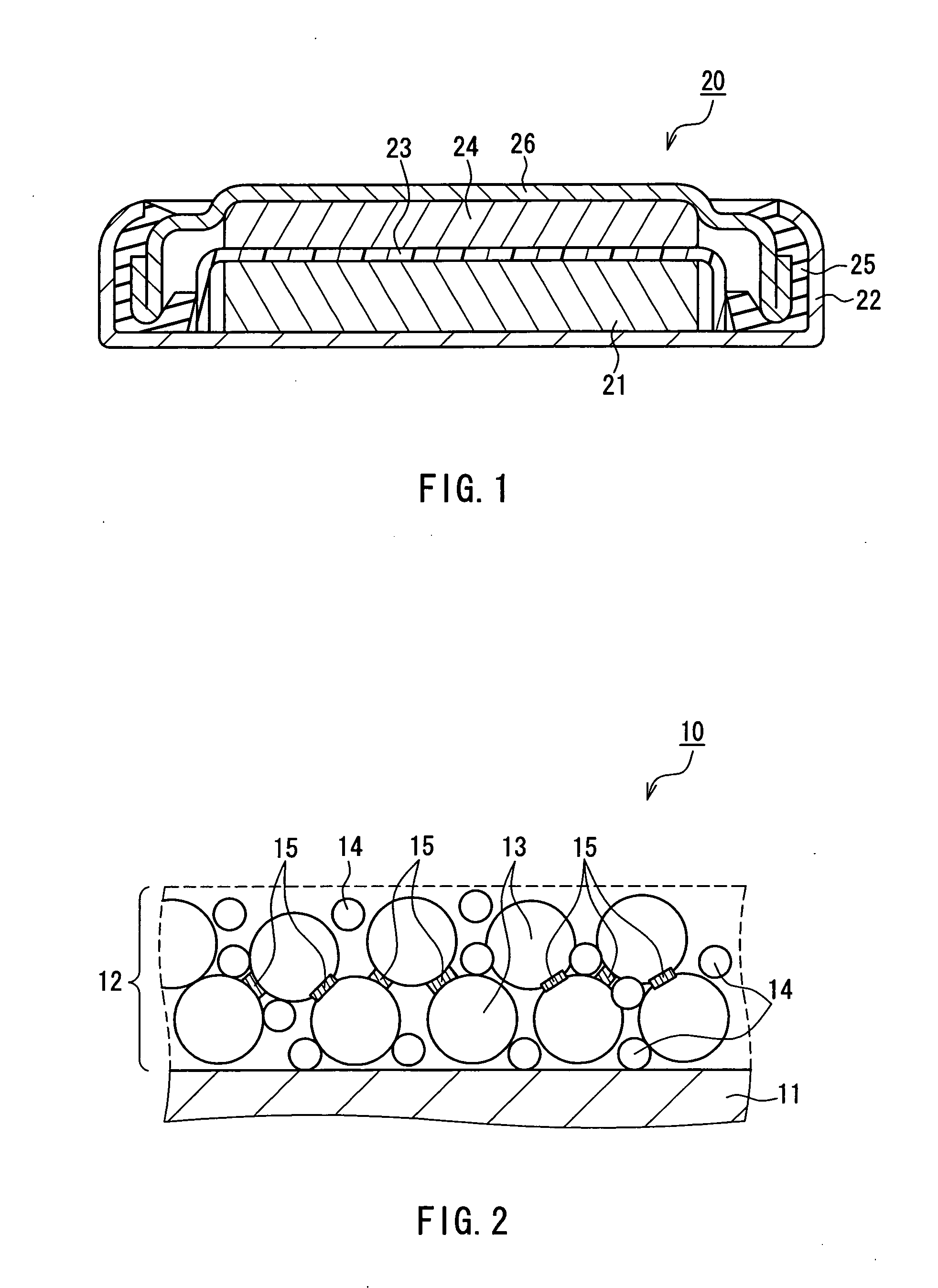
Image


Examples
example 1
[0130] Subsequently, Samples as examples (Samples 1 to 28) were manufactured.
[0131] Firstly, a negative electrode active material was prepared, which was used in Comparative Example Sample 108 and whose composition was Si—Ti. This active material was charged into an Atrita Ball Mill together with balls made of zirconia (ratio of active material:balls=1:3 (mass ratio)), and powder of an element R shown in Table 2A was added thereto in the amount of addition shown in Table 2A. The amount of addition of an element R in Table 2A shows the amount when the total of Si and Ti as a transition metal element M is defined as 100 mass parts. This also applies to the subsequent tables. As powder of the element R, the following were used: for Sn powder, powder of 99.9% purity and 2 μm in average particle diameter was used. For In powder, powder of 99.9% purity and 4 μm in average particle diameter was used. For Ga powder, powder of 99.9% purity and 4 μm in average particle diameter was used. For...
example 2
[0144] Subsequently, samples as examples (Samples 29 to 32) were manufactured.
[0145] Firstly, negative electrode active materials were prepared, which were used for Comparative Example Samples 106, 111, 113 and 114. 10 mass parts of Sn powder (purity: 99.9%, average particle diameter: 2 μm) was added to these active materials. Subsequently, these mixed powders were subjected to mechanical milling for 1 hour under the same conditions as those for Samples 1 to 28, so that negative electrode active materials for Samples 29 to 32 were manufactured. Table 3A shows the list of these samples.
TABLE 3AAmountofelementActual contentAvg.R addedofOxygenparticleSampleCompositionMSi(masselement RamountdiameterNo.Si—Mmass %mass %Element Rparts)(mass %)(mass %)(μm)29Si—Cu4258Sn106.91.22.230Si—Ni4654Sn107.41.43.131Si—Co4654Sn108.213.432Si—Fe4555Sn107.61.52
[0146] Next, using the thus obtained Samples 29 to 32, negative electrodes were manufactured in a similar manner to Comparative Example 1. Subse...
example 3
[0153] Firstly, a negative electrode active material used for Comparative Example Sample 108 was prepared (composition of Si—Ti). Next, Sn or In as the element R was attached by plating to the surface of this active material. Before conducting the plating of Sn and In, the surface of the active material was activated (application of Pd catalyst) as a pretreatment, and Cu-plating was performed by electroless plating as a primary coat. Sn-plating was performed by impregnating the Cu-plated active material with an electroless plating solution of Sn (pH=1.8, plating temperature: 40° C.) for 30 minutes. In-plating was performed by impregnating the Cu-plated active material with an electroless plating solution of In (pH=12, plating temperature: 25° C.) for 30 minutes. After plating Sn or In, the active material was washed with distilled water three times, which was then dried in a vacuum atmosphere at 110° C. for 10.5 hours, so that negative electrode active materials for Samples 33 to 42...
PUM
| Property | Measurement | Unit |
|---|---|---|
| diameter | aaaaa | aaaaa |
| temperature | aaaaa | aaaaa |
| temperature | aaaaa | aaaaa |
Abstract
Description
Claims
Application Information