Shock dampening biocompatible valve

a biocompatible valve and shock-dissipating technology, applied in the field of prosthetic valves, can solve the problems of mechanical valve noise, various problems and deficiencies, and the formation of potentially damaging blood clots in the recipient patient, and achieve the effect of discharging hydraulic shock energy

Active Publication Date: 2006-07-06
SIERACKI JEFFREY M
View PDF27 Cites 73 Cited by
  • Summary
  • Abstract
  • Description
  • Claims
  • Application Information

AI Technical Summary

Benefits of technology

[0023] In still another aspect of the invention, a biocompatible valve is provided that includes a valve body affixable to the organism and operable to allow the fluid to flow along in a longitudinal axis thereof. The valve body has formed in opposing relationship thereon a first and second aperture for allowing the fluid to flow longitudinally through an orifice defined therebetween. The valve also includes a closing mechanism coupled to the valve body and positioned in the valve body and operable into one of a closed and open position. The closing mechanism has a closed surface on which at least a portion thereof is longitudinally displaceable in the valve body so as to dissipate hydraulic shock energy at the orifice resultant from an interruption of the fluid flow by a transition of the closing mechanism from the open to the closed position.

Problems solved by technology

Both of these options suffer from various problems and deficiencies.
Mechanical valves, due to the presence of fixed hard edges and other biological incompatibility factors, are prone to the formation of potentially damaging blood clots in the recipient patient.
Of these drawbacks, mechanical valve noise has been brought forward as a prominent complaint by many mechanical valve recipients.
Mechanical valves by contrast, due to limitations of manufacturing processes and materials, can be quite noisy.
Noise problems are compounded in the presence of a graft, such as an aortic root replacement, that removes the acoustic and shock absorptive properties normally afforded by the surrounding natural tissue structures.
Unfortunately, it is common for both the ascending aorta and aortic valve to be replaced simultaneously in the same operation, such as for patients with an aortic aneurysm.
Generally, mechanical valves are composed of metals, carbon composites, pyrolytic carbon, or various hybrid combinations that are fairly stiff and durable, but the closing of these valves introduces noise that is both heard and felt by mechanical valve recipient patients.
Since these valves close under considerable pressure, the impact forces can be substantial and the resulting sound may be quite loud.
A second component of valve noise arises from the phenomena of hydraulic shock.
In plumbing, a similar phenomenon is referred to as “water hammer” and the forces generated are known by plumbers to be potentially damaging in magnitude.
Nonetheless, shock noise is a persistent complaint in patients.
Additionally, the hydraulic shock is sometimes extremely strong and has very low frequency components that may present an uncomfortable physical “thumping” sensation in the chest wall.
Psychoacoustic stress notwithstanding, the hydraulic shock involved in these mechanical replacement valves present physical forces that may very well shorten the life of the valve and may cumulatively damage major blood vessels or other body tissue.
The hydraulic shock is a particular problem in aortic valve replacements in that the aortic valve is situated between the final pumping chamber of the heart and the aorta.
The mechanical valve, however, generates a much more abrupt interruption of flow than a tissue valve due to the stiffness of the components composing the valve.
Natural structures may be inadequate for absorbing the shock.
Furthermore, when a synthetic arterial graft is introduced with the mechanical valve, as is common in aortic aneurysm repair, the combined system loses many of the natural dampening features and the problem is significantly worsened.
Secondly, the elasticity dampens shock waves that would otherwise resonate through the system had a stiff tube been implemented for the artificial aorta.
The design illustrated in FIGS. 1A-1B is not optimized to effectively dampen hydraulic shock.
Furthermore, the shockwave caused by the mechanical transition of state of the valve will be only partially damped by the elastic walls.
Thus, dampening will not be optimal.
Moreover, the elastic expansion occurs perpendicular to blood flow, i.e., in a radial direction, and is therefore not well suited to absorbing shock energy from a compression wave moving longitudinally through the system.
An additional problem arises with artificial sinuses in that they are susceptible to scarring.
This fibrous tissue is much less flexible than the natural arterial walls and less flexible than the artificial sinus cavity walls.
Should the walls stiffen to a point where they are maintained in a position that causes blood to eddy, the resulting hemodynamics may lead to increased clot formation in the region.
Additionally, the use of an artificial sinus only applies to patients that are receiving an aortic graft in addition to a replacement valve.

Method used


Image

  • Shock dampening biocompatible valve
  • Shock dampening biocompatible valve
  • Shock dampening biocompatible valve

Examples


Embodiment Construction

[0037] Various exemplary embodiments of the present invention will now be described in conjunction with the illustrations of the Drawings. It is to be understood that the Drawings are not scaled mechanical drawings, but are diagrams intended to show the combination of features which form the invention when embodied as depicted.

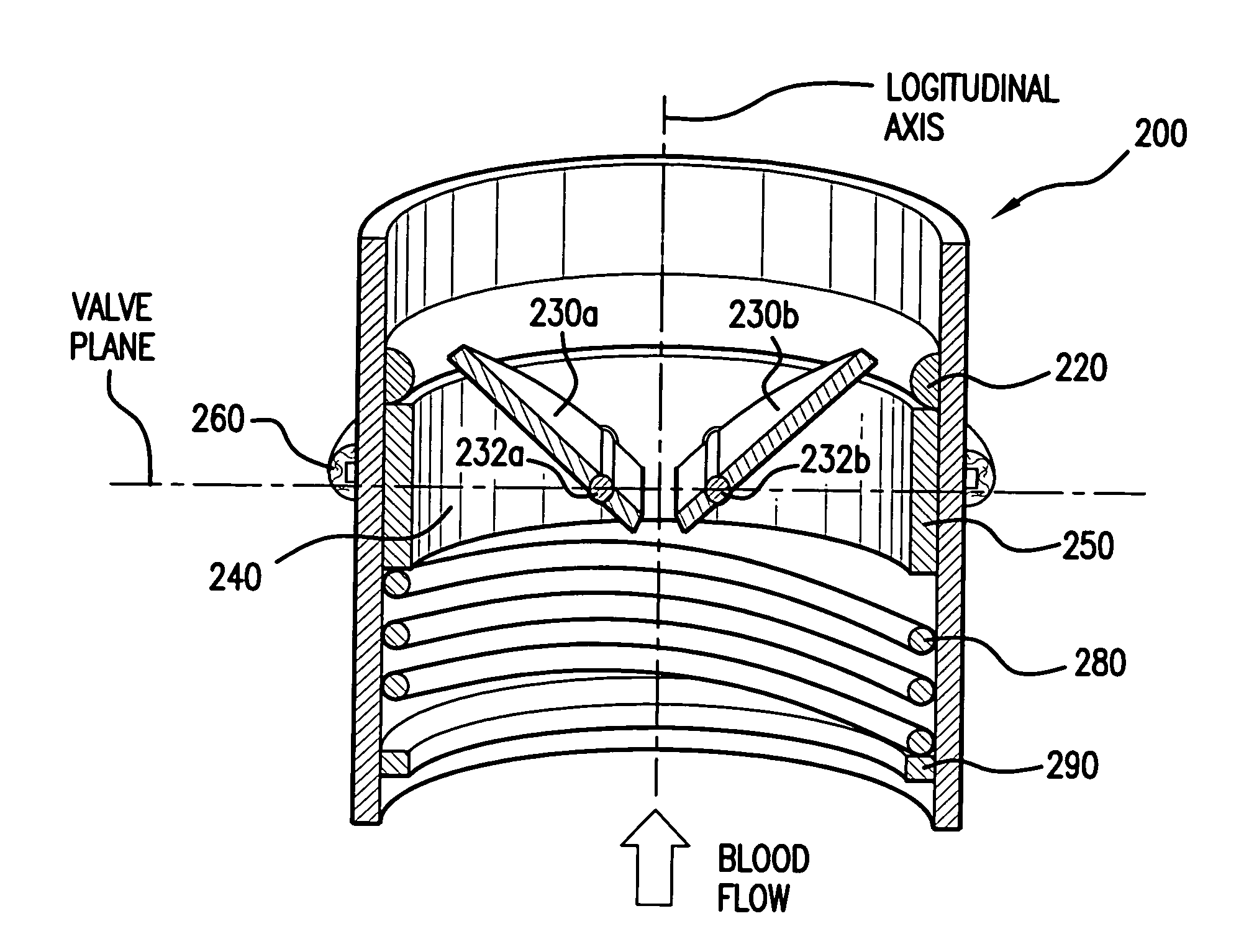
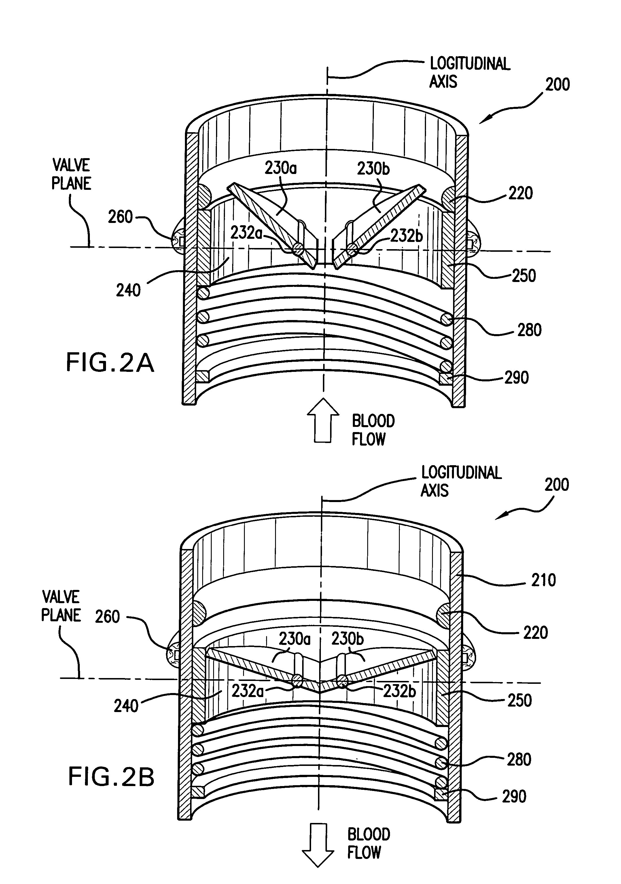
[0038] Referring to FIGS. 2A and 2B, there is shown in cross-section a biocompatible valve 200 operable in accordance with the invention. As is shown in the Figure, the valve 200 includes a mount 210 having a longitudinal axis along which blood flows. The mount 210 is affixable to the patient by affixing means, which may be any known means for affixing a replacement valve into a patient known in the art, such as by suture cuff 260. Additionally, the affixing means need not be located at the midpoint as shown in the Figure. In certain embodiments of the invention, the valve 200 will be formed into or make a part of an aortic graft in which case the suture cuff...


PUM


Abstract

A biocompatible valve (200) includes a valve mechanism (250, 230a, 230b), which is mounted and is longitudinally displaceable within a valve mount (210) affixed to a recipient patient. A valve annulus (250) defines an orifice (240) in which a closing mechanism (230a, 230b) is received. Upon a transition from an open position to a closed position of the closing mechanism (230a, 230b), hydraulic shock is introduced into the fluid passing through the valve. The present invention provides a dampening mechanism (280) to mitigate the shock and to dissipate its energy. Various embodiments allow for high order frequency response through relationships between dampening mechanism components.

Description

RELATED APPLICATION DATA [0001] This Patent Application is based on a Provisional Patent Application Ser. No. 60 / 640,499, filed on 30 Dec. 2004.BACKGROUND OF THE INVENTION [0002] 1. Field of the Invention [0003] The invention described herein is directed to prosthetic valves, such as mechanical heart valves adapted for surgical implantation to a patient. More specifically, the invention is operable to mitigate audible noise, physical discomfort, and mechanical stress on both the replacement valve and patient tissues that is caused from hydraulic shock in the fluid when the valve through which the fluid flows undergoes a transition from an open position to a closed position. [0004] 2. Brief Description of the Prior Art [0005] The surgical replacement of natural heart valves with durable, artificial valves in living patients has become commonplace due to the reliability of such valves achieved in the past several decades. Among the prosthetic replacement valve options are “tissue valv...

Claims


Application Information

Patent Timeline
Patent Type & Authority Applications(United States)
IPC IPC(8): A61F2/24
CPCA61F2/2403
Inventor SIERACKI, JEFFREY M.
Owner SIERACKI JEFFREY M
Why Eureka
Try Eureka