Combustible gas detection system

a detection system and combustible gas technology, applied in the direction of electrochemical generators, instruments, electrolysis components, etc., can solve the problem of low monitoring performance than is desired

Inactive Publication Date: 2006-07-13
PROTON ENERGY SYST
View PDF20 Cites 13 Cited by
  • Summary
  • Abstract
  • Description
  • Claims
  • Application Information

AI Technical Summary

Problems solved by technology

Unfortunately, since the gas stream can still have a relative humidity greater than 95%.
This high relative humidity results in lower monitoring performance than is desired.

Method used


Image

  • Combustible gas detection system
  • Combustible gas detection system
  • Combustible gas detection system

Examples


Embodiment Construction

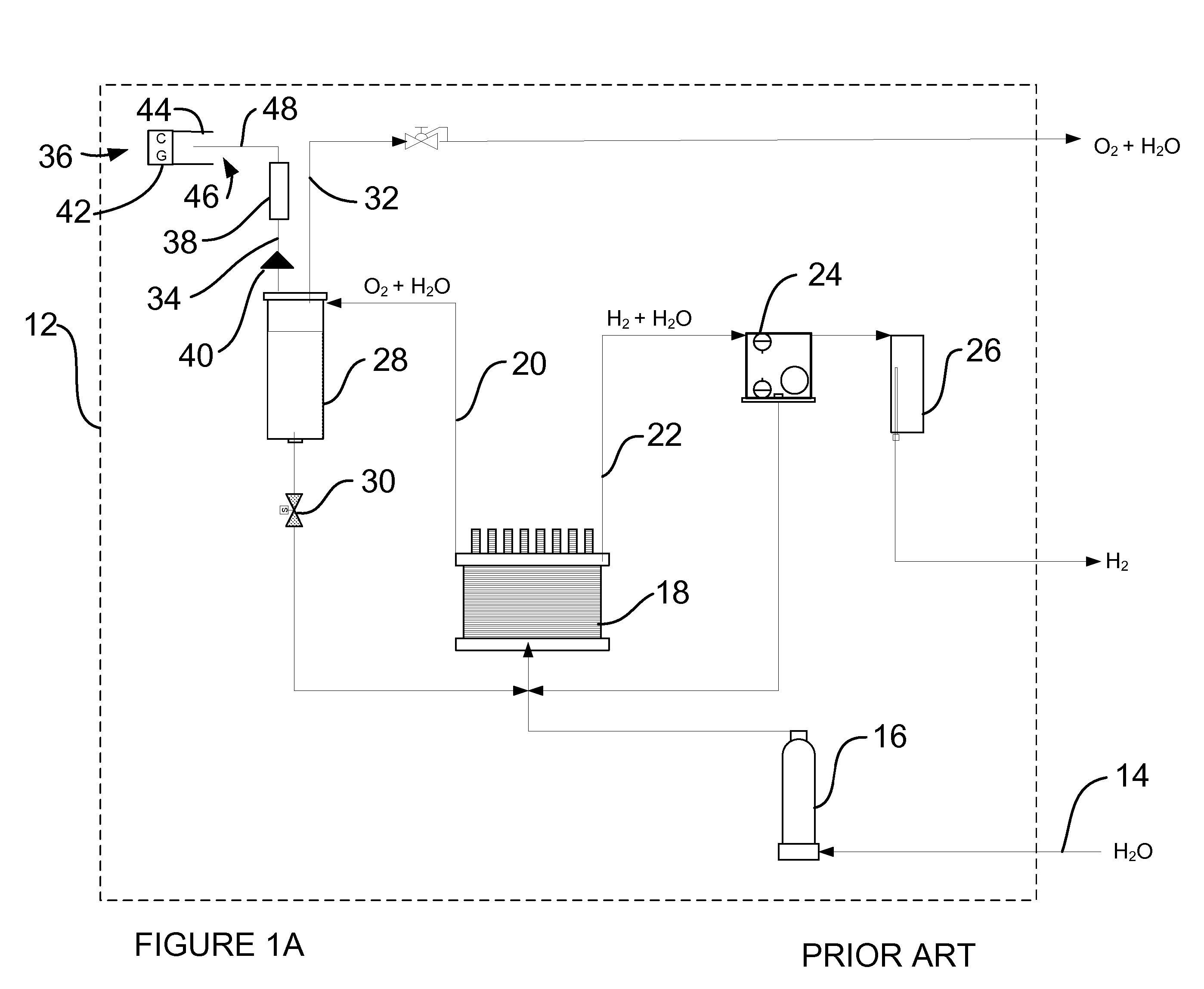
[0020] Hydrogen gas is a versatile material having many uses in industrial and energy application ranging from the production of ammonia, to power vehicles being propelled into space. Since the hydrogen molecule is one of the smallest known particles, containing and controlling leaks of hydrogen gas is very difficult. Monitoring of these leaks is important as it is typically an indicator of performance degradation and or component wear. Typically, prior art systems have used combustible gas sensors to monitor levels of combustible gas in the system. When unacceptable levels of hydrogen are detected in the system, the system is either shut down, or the operator is alerted that preventative maintenance is required.

[0021] Commercial combustible gas sensors typically use a technology referred to as a “catalytic bead” type sensor, such as the Detcon, Inc. Model FP-524C. These sensors monitor the percentage of lower explosive limit (“LEL”) of combustible gas in a product gas stream. This...


PUM

PropertyMeasurementUnit
metallicaaaaaaaaaa
electricalaaaaaaaaaa
purityaaaaaaaaaa

Abstract

A system is provided for monitoring the levels of combustible gas in a gas stream. The system includes means for controlling the relative humidity of the gas stream and maintain a humidity level in the performance range of combustible gas sensors. A number of methods are illustrated for achieving the humidity control including secondary phase separations and the adjusting of the gas stream temperature.

Description

CROSS REFERENCE TO RELATED APPLICATIONS [0001] This application is a continuation of U.S. patent application Ser. No. 10 / 707,324 which was filed on Dec. 5, 2003FIELD OF THE INVENTION [0002] This disclosure relates generally to the detection of combustible gases, and especially relates to the detection of hydrogen in a vent gas stream. BACKGROUND OF THE INVENTION [0003] Hydrogen gas is used and produced in many applications. Since the amount of hydrogen in a gas stream produced by a given process may be an indicator of system efficiency, the systems typically utilize sensors, such as combustible gas sensors to determine the level of hydrogen. An example of a prior art system having an arrangement for monitoring combustible gas is shown in FIG. 1A. The electrochemical system 12 receives water from an external source 14 and passes it through a deionizing bed 16. Once the water has been properly conditioned, it is supplied to an electrochemical cell 18 which disassociates the water into...

Claims


Application Information

Patent Timeline
Patent Type & Authority Applications(United States)
IPC IPC(8): C25B1/02
CPCC25B1/04C25B9/10C25B15/02H01M8/0656Y02E60/366C25B9/23Y02E60/36Y02E60/50
Inventor STULL, JEFFREYBALTRUCKI, JUSTINSTANEK, ANDRZEJDEMAREST, EDWARDKOOPMAN, JOHNRABBETT, DANIEL
Owner PROTON ENERGY SYST
Why Eureka
Try Eureka