Method of producing oxide soot using a burner with a planar burner face

a burner and burner face technology, applied in the field of burners, can solve the problems of reducing the soot deposition rate, defective or unusable optical waveguides, and imperfections in the preform, and achieve the effects of less soot waste, accurate and efficient deposition of metallic oxide soot, and high back pressur

Inactive Publication Date: 2005-01-04
CORNING INC
View PDF26 Cites 51 Cited by
  • Summary
  • Abstract
  • Description
  • Claims
  • Application Information

AI Technical Summary

Benefits of technology

The present invention provides a burner and method that allows for distributed, even flow of each of the precursor and gasses passing through the burner and exiting a burner face defined by the planar surface of one of the planar layers. The distributed, even flow is a result of openings through at least a portion of the layers that are small enough to create a high back pressure and equalize the flow through the openings. Preferably, the small openings that create the back pressure are in a distributor layer or a layer defining the burner face. In addition, the present invention provides a burner having orifices and channels that can be fabricated on a micron scale to enable more accurate and efficient deposition of metallic oxide soot on a receptor surface. Such accurate deposition will enable a greater percentage of soot to be captured on a receptor surface such as a mandrel, and consequently, result in less soot waste due to soot not reaching the intended receptor surface. In waveguide manufacturing processes, increased deposition accuracy and efficiency also enable improved refractive index profile control during the manufacture of optical waveguides.

Problems solved by technology

This gelling reduces the soot deposition rate, and during optical waveguide preform manufacture, leads to imperfections in the preform that will produce defective or unusable optical waveguide.
One disadvantage of current burner design is that it is very difficult to manufacture burners for deposition of metal oxide soot having orifices and supply channels on a miniaturized scale, i.e. channels and orifices having widths or diameters less than 150 microns.
Variability of mass produced parts is also problem with current burner technology, in addition to the cost in machining precision channels and orifices on a miniaturized scale.
The larger droplets are difficult to combust, and uncombusted droplets can cause defects in the product made by the deposited soot.

Method used


Image

  • Method of producing oxide soot using a burner with a planar burner face
  • Method of producing oxide soot using a burner with a planar burner face
  • Method of producing oxide soot using a burner with a planar burner face

Examples


Embodiment Construction

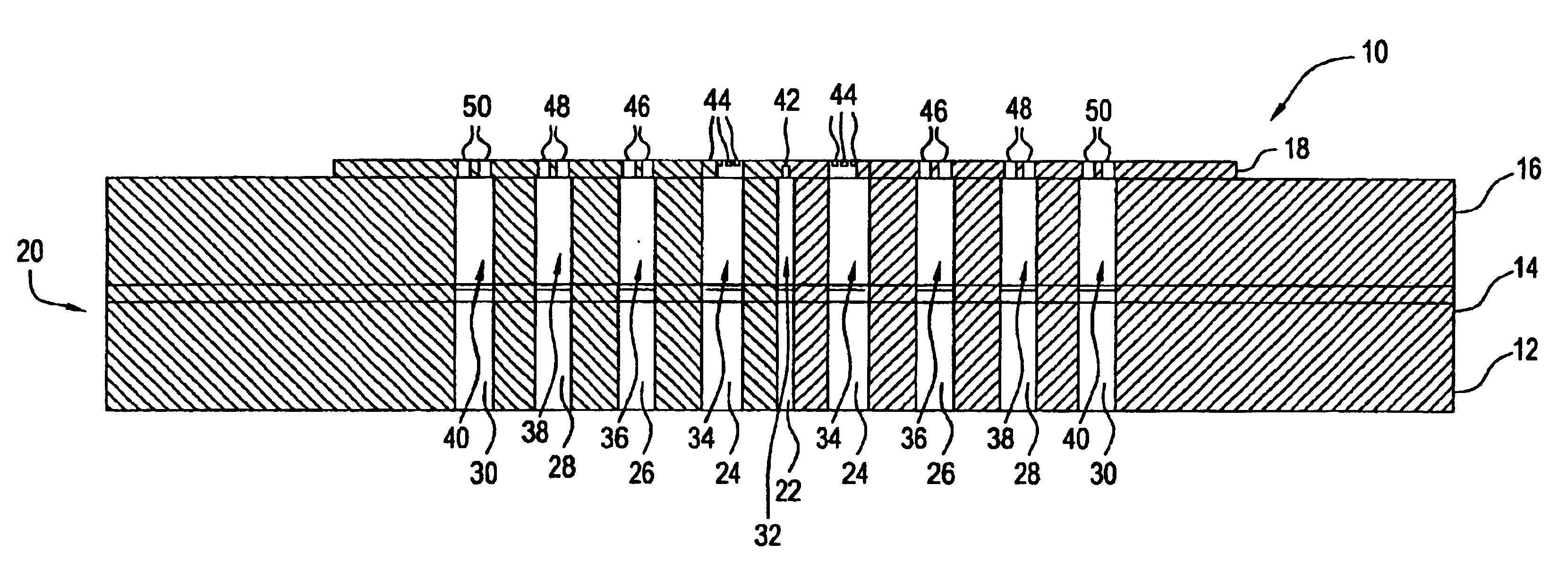
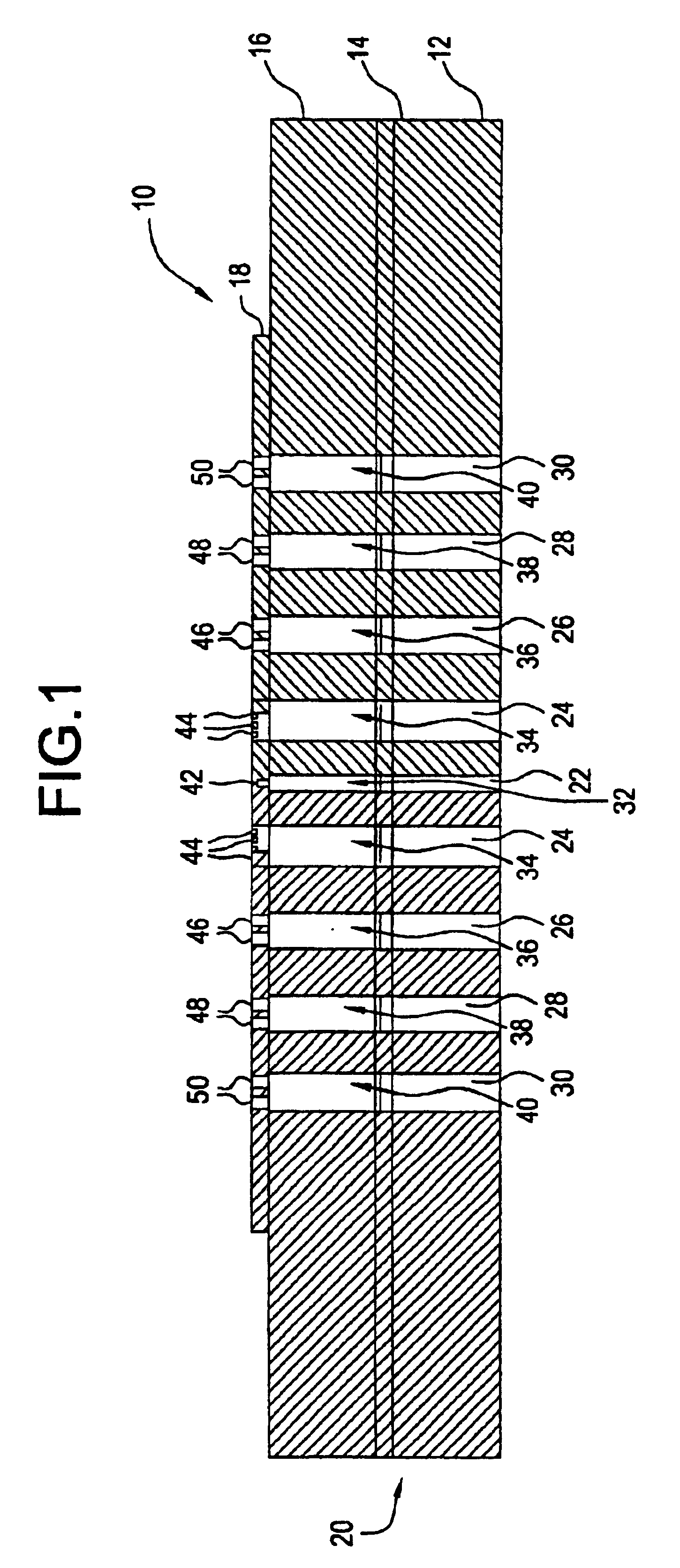
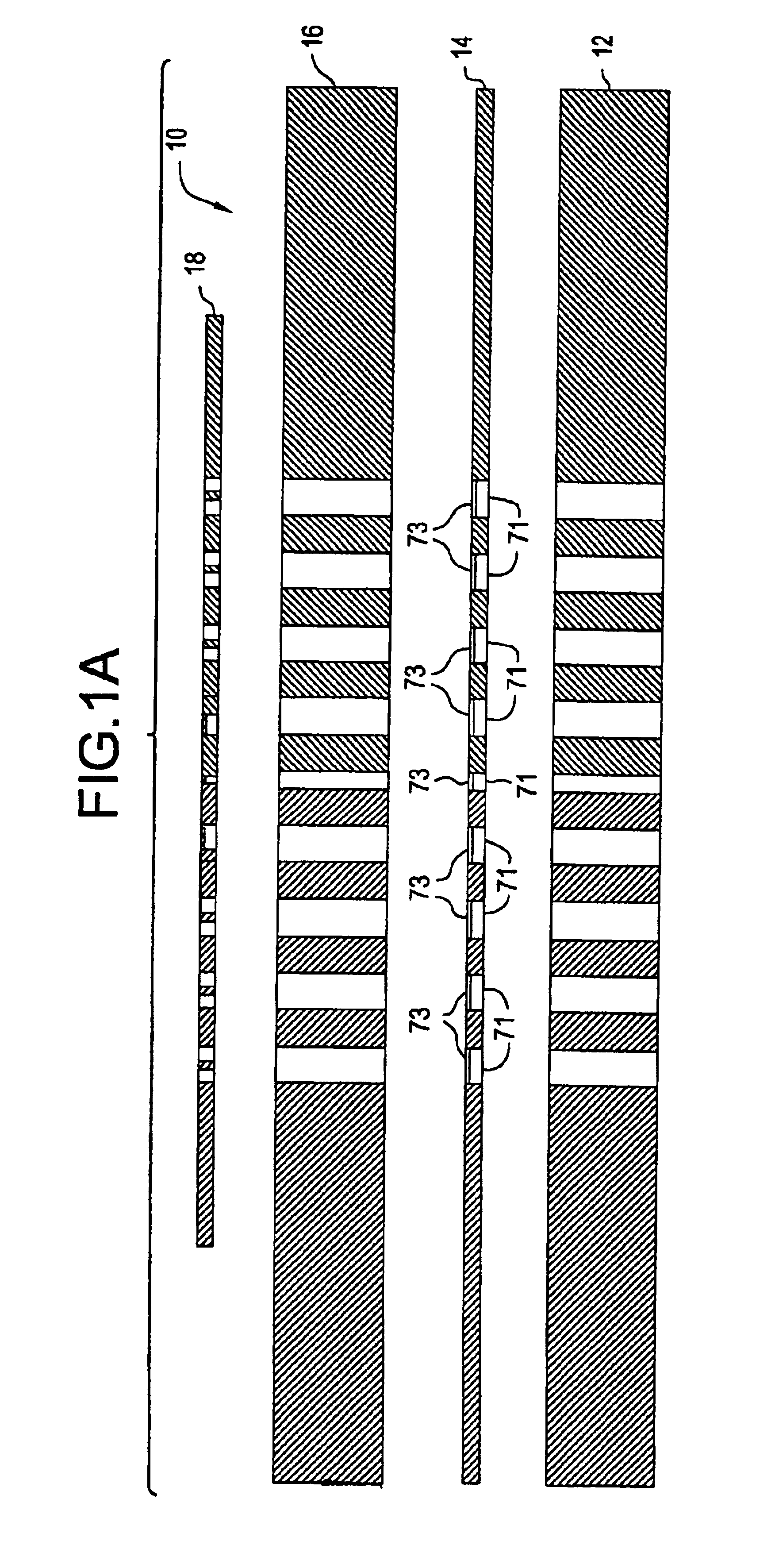
An exemplary embodiment of the burner of the present invention is shown in FIG. 1 and FIG. 1A and is designated generally by reference numeral 10. The burner 10 is a burner for producing a flame from a combustible gas in which a precursor undergoes a chemical reaction to form an inorganic soot, preferably a metallic oxide soot. In an exemplary, preferred embodiment of the present invention the burner is used to produce doped or undoped silica soot by reacting a silicon-containing precursor in the flame produced by the burner 10.

The burner 10 comprises a plurality of substantially planar layers arranged in a generally parallel and fixed relationship. Each layer is preferably at least about 100 microns to about 1 millimeter thick, and the length and width of each layer will depend on the particular application for which the burner is used. For example, burners used for the production of silica soot for waveguide fiber preform may be approximately 1 centimeter wide and one centimeter l...


PUM

PropertyMeasurementUnit
diametersaaaaaaaaaa
diametersaaaaaaaaaa
temperatureaaaaaaaaaa

Abstract

A burner and a method for producing an inorganic soot such as silica comprising a plurality of substantially planar layers having multiple openings therethrough formed by a micromachining process. The openings are in fluid communication with a precursor inlet and a gas inlet to permit the gas and the precursor to flow through and exit the burner. The burner produces a flame from a combustible gas in which the precursor undergoes a chemical reaction to form the soot.

Description

FIELD OF THE INVENTIONThe present invention relates to burners for producing inorganic soot. More particularly, the present invention involves burners for producing a flame in which a precursor material undergoes a chemical reaction to form a metal oxide soot.BACKGROUND OF THE INVENTIONThe formation of inorganic soot, particularly metallic oxide soot, produced by reacting a precursor in the flame of a burner is well known. For example, soot generated by such a reaction has been used to form articles such as crucibles, tubing, lenses, and optical waveguides by depositing the soot on a receptor surface.This process is particularly useful for the formation of optical waveguide preforms made from doped and undoped silica soot, including planar waveguides and waveguide fibers. The waveguide formation process generally involves delivering a silicon-containing precursor to a burner and reacting the precursor in a burner flame generated by a combustible gas such as a mixture of methane and ...

Claims


Application Information

Patent Timeline
Patent Type & Authority Patents(United States)
IPC IPC(8): C03B19/00C03B37/014C03B19/14F23D14/14C01B13/20C01B33/18C03B8/04F23D14/56F23D14/58F23D99/00H04R29/00
CPCC03B19/1423C03B37/0142F23D14/56F23D14/58C03B2207/02F23D2203/102C03B2207/42C03B2207/34C01B13/20C01B33/18C01B33/183C03B2207/32F23D91/02C03B19/14
Inventor HAWTOF, DANIEL W.
Owner CORNING INC
Why Eureka
Try Eureka