Method for extracting shale oil and gas from oil shale in situ

A technology for shale oil, gas and oil shale, applied in the field of oil shale mining, can solve the problems of restricting large-scale promotion, high acid waste water, high polluting gas, etc., to reduce costs and risks, reduce construction difficulty and expenses, increase The effect of a large reaction area

Active Publication Date: 2014-04-02
JILIN UNIV +1
View PDF8 Cites 49 Cited by
  • Summary
  • Abstract
  • Description
  • Claims
  • Application Information

AI Technical Summary

Problems solved by technology

The surface dry distillation method will bring highly polluting gases, highly acidic wastewater and waste

Method used


Image

  • Method for extracting shale oil and gas from oil shale in situ
  • Method for extracting shale oil and gas from oil shale in situ
  • Method for extracting shale oil and gas from oil shale in situ

Examples


Embodiment 1

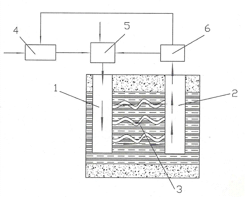
[0046] The buried depth of oil shale in a certain place is 380m-390m, the cover layer is 5m thick, the weakly weathered layer is 5-7m, the average oil content is 6%, the water content is 5%, and the fixed carbon is 15%. The roof and floor are both dense shale. The implementation steps are as follows:

[0047] (1) Drilling and completion

[0048] a. According to the distribution and direction of the oil shale layer, the distance between the heat injection well and the production well is selected to be 15m;

[0049] b. Drill a heat injection well 1 on the ground to 393m underground, and pass through the oil shale layer. The heat injection well 1 adopts a well structure with at least three openings, one opening to 10m below the floor of the overlying soft layer, and the second opening to the oil shale layer 378m, three to 393m;

[0050] c. Establish a fracturing chamber in the heat injection well 1, take out the drilling casing, and squeeze the high-pressure, large-displacemen...

Embodiment 2

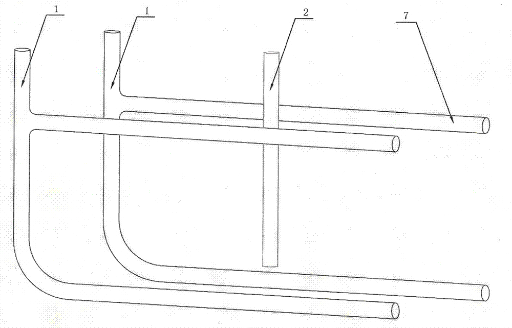
[0071] figure 2 Be embodiment 2, be the directional horizontal well form; The concrete steps of the present embodiment are as follows:

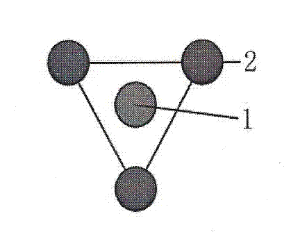
[0072] a. According to the distribution and trend of the oil shale layer, select the specific location of the heat injection well and the production well, arrange two heat injection wells 1 and one production well 2 in the delineated working area, and place each heat injection well 1 in the oil shale layer Two horizontal wells 7 are arranged in the vertical direction, and the distance between adjacent heat injection wells 1 is 25m;

[0073] b. Drill the thermal injection well 1 on the ground to the bottom plate of the oil shale layer, and continue to drill two horizontal wells 7 in two directions parallel to and close to the top plate of the oil shale layer and the bottom plate of the oil shale layer after passing through two certain turning radii;

[0074] c. Establish a fracturing chamber in a horizontal well connected to the heat injecti...


PUM


Abstract

The invention discloses a method for extracting shale oil and gas from oil shale in situ. The method comprises the steps that hot nitrogen is injected into an oil shale layer to crack kerogen in situ; after being extracted and separated, combustible gas which is generated initially is injected into a well together with the nitrogen by a certain proportion to have chemical reaction with the oil shale, so as to further crack organic substances in the oil shale, and extract shale oil and combustible gas; the hot nitrogen is an inert gas which is not only a carrier for transferring heat but also a carrier which carries shale oil and gas to above the ground; meanwhile, due to the pressure action of fluid, an oil and gas channel is favorably formed in the oil shale layer. The circulating combustible gas can have chemical reaction with the kerogen in the oil shale, so as to accelerate the reaction. According to the method for extracting shale oil and gas from the oil shale in situ, mining cost and risks are greatly reduced, the operability is greatly improved, problems caused by a surface dry distillation technology and an existing in-situ technology are fundamentally solved, the construction difficulty and cost are effectively reduced, and the method does not pollute underground water, is environment-friendly and is non-toxic.

Description

technical field [0001] The invention relates to an oil shale mining technology, in particular to a method for extracting shale oil and combustible gas by injecting high-temperature nitrogen gas and hydrocarbon circulating gas into oil shale in situ. Through combustion and reuse of combustible hydrocarbon cracking gas in the process and cracking reaction to complete regional high waste heat recycling, the energy self-sufficiency and maximum utilization of oil shale cracking can be realized. This technical method can be widely used in in-situ mining of solid or condensed mineral fuels (oil shale, coal, heavy oil). Background technique [0002] Fossil energy is a non-renewable energy source. According to data from the US Geological Bureau, based on the current oil extraction, the largest scale of oil production will appear in the 1930s. By the middle of this century, the available oil resources will towards exhaustion. If the current production rate is maintained, natural gas...

Claims


Application Information

Patent Timeline
IPC IPC(8): E21B43/241
Inventor 孙友宏李强阿龙.巴尔白奉田郭威刘宝昌郭明义侯传彬王秋雯高科
Owner JILIN UNIV
Why Eureka
Try Eureka