Rotary carburetor

a rotary carburetor and carburetor body technology, applied in the direction of heating types, separation processes, applications, etc., can solve the problems of restricting the layout of other auxiliary equipment and component parts, inconvenient adjustment work, etc., to improve work efficiency, simplify manufacturing assembly, and improve packaging versatility for engine applications

Inactive Publication Date: 2006-07-13
WALBRO ENGINE MANAGEMENT
View PDF7 Cites 8 Cited by
  • Summary
  • Abstract
  • Description
  • Claims
  • Application Information

AI Technical Summary

Benefits of technology

[0011] Objects, features and advantages of this invention include a carburetor with multiple adjustments that are all adjustable from a single direction improving packaging versatility for an engine application. Other advantages include simplified manufacturing assembly, improved work efficiency when adjusting fuel and air flow through the carburetor, and easy disassembly for cleaning and maintenance of internal components such as the fuel feed tube while protecting and making other components less susceptible to damage. The carburetor is of relatively simple design, economical manufacture and assembly robust, reliable, durable and in service has a long useful life.

Problems solved by technology

Unfortunately, access to the high speed adjustment needle must be provided on the side of the carburetor body and not the top like the idle adjustment needle because the top is generally congested with the cover, throttle lever and cam mechanism of the carburetor.
Therefore, when conducting the idle and high speed calibration and operation tests of the carburetor in the assembly line or at the time of servicing, the adjustment must be conducted from two different directions, and this inconveniently complicates the adjustment work.
This restricts the layout of other auxiliary equipment and component parts.

Method used


Image

  • Rotary carburetor
  • Rotary carburetor
  • Rotary carburetor

Examples


Embodiment Construction

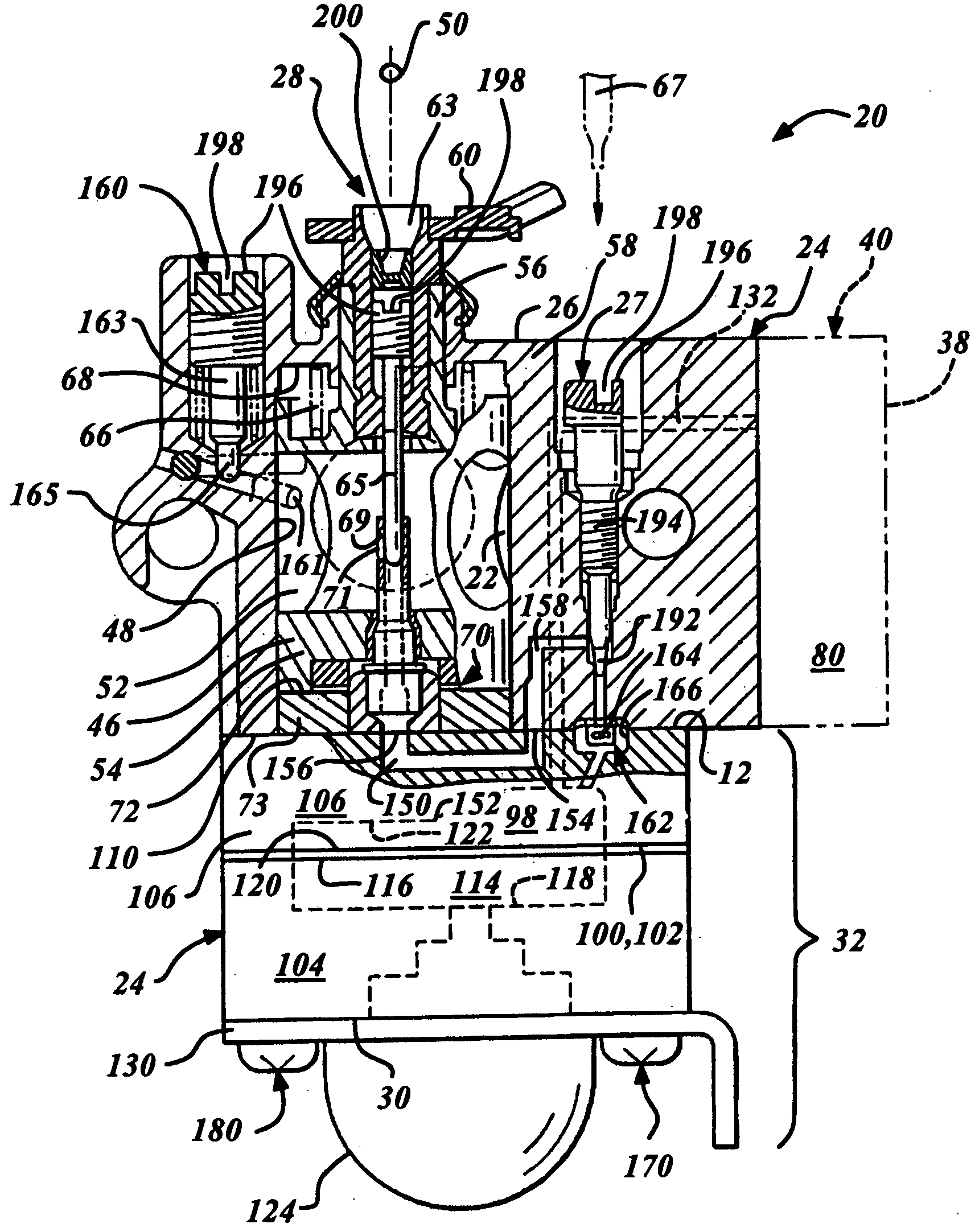
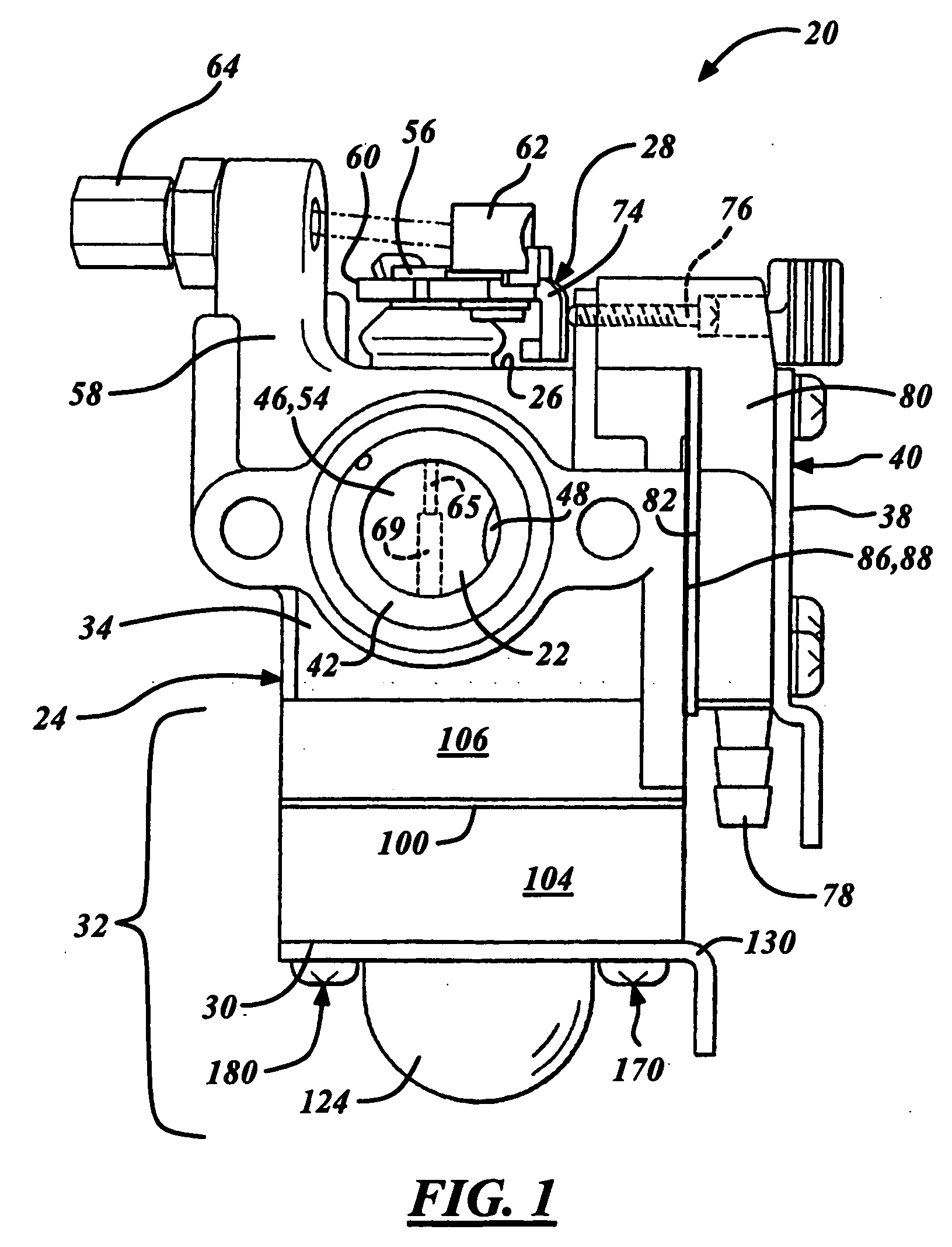
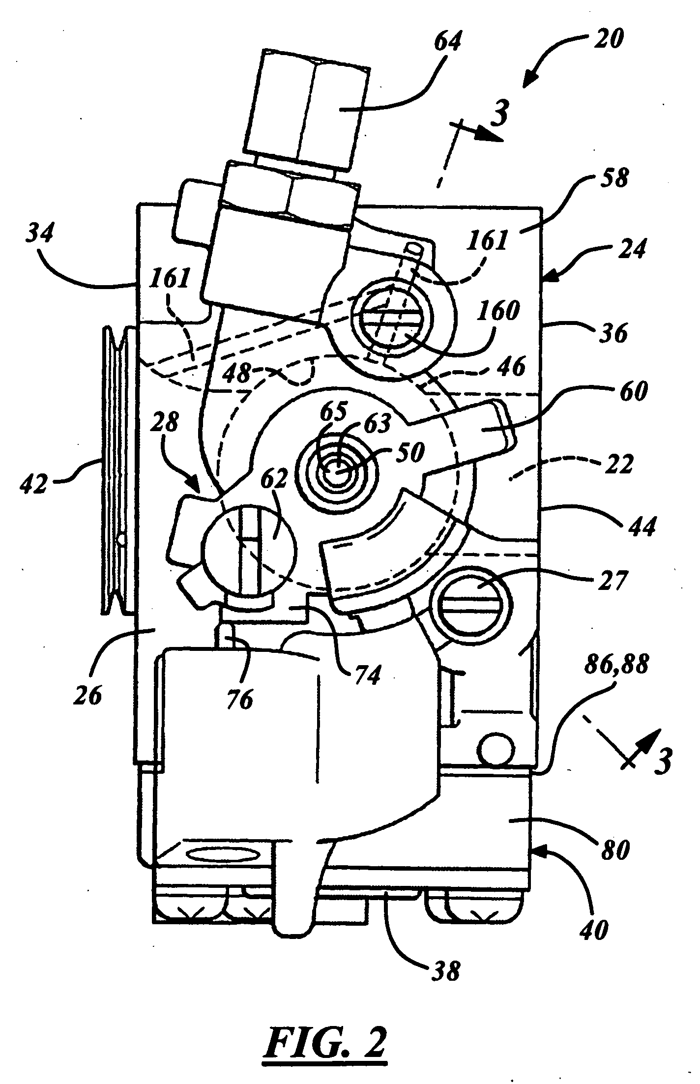
[0019] As best illustrated in FIGS. 1-4, a diaphragm carburetor 20 embodying the present invention is preferably of a rotary type and has a fuel-air mixing passage 22 extending through a main body 24 for the flow of a mixture of fuel and air to a running combustion engine. As illustrated and orientated for the sake of explanation, the main body 24 has an external top surface 26 through which a rotary throttle valve 28 projects and exposes a fuel idle adjustment needle 65 for operator access and adjustment. Also accessible through or above the top surface 26 is a fuel high speed adjustment needle 27, and preferably an air bypass screw 160 and an idle adjustment screw 76. Having generally all of the carburetor adjustments located on one surface or side of the carburetor body 24, increases versatility of carburetor packaging in an engine driven aparatus, simplifies end user or operator adjustments and improves manufacturing assembly and efficiency.

[0020] The main body 24 also has an e...


PUM

PropertyMeasurementUnit
speedaaaaaaaaaa
areaaaaaaaaaaa
speedsaaaaaaaaaa

Abstract

A versatile rotary carburetor has an idle adjustment needle, a high speed adjustment needle, and preferable an air bypass screw which are substantially parallel to one another and are axially exposed for adjustment in a substantially common direction. Preferably a cammed rotary throttle valve is seated in a body of the carburetor for rotation about and axial movement along an axis. The rotary throttle valve intersects a mixing passage in the body, and carries a through-bore that variably generally aligns to the mixing passage upon rotation of the throttle valve. The throttle valve projects axially through an external surface of the body and threadably receives the idle adjustment needle oriented concentrically to the axis. A primary fuel feed tube disposed concentrically to the axis projects into the through-bore to receive the idle adjustment needle at an open distal end which variably obstructs an orifice in a cylindrical wall of the tube that generally communicates with the through-bore for delivering liquid fuel to the mixing passage. The high speed adjustment needle is preferably threaded to the body for adjustably intersecting and obstructing a fuel passage in the body that flows liquid fuel to the fuel feed tube for the flow of liquid fuel. Preferably, the air bypass screw threads into the body for adjustably intersecting and obstructing an air bypass passage in the body communicating at both ends with the mixing passage for generally bypassing the rotary throttle valve when in an idle position.

Description

RELATED APPLICATIONS [0001] Applicants claim priority of Japanese Application Ser. No. 2005-070771 filed on Mar. 14, 2005 and Japanese Application Ser. No. 2005-003355 filed on Jan. 11, 2005. FIELD OF THE INVENTION [0002] The present invention relates generally to a carburetor for a combustion engine and more particularly to a rotary carburetor. BACKGROUND OF THE INVENTION [0003] Known rotary type carburetors are commonly used for small, two stroke combustion engines applied to applications such as handheld chainsaws, leaf blowers, hedge trimmers, and the like. A rotary throttle valve of the carburetor has a generally cylindrical throttle received rotatably in a cylindrical cavity of a body that intersects a fuel-and-air mixing passage extending through the body. The rotary throttle valve rotates about an axis and, via a cam interface between the body and the cylindrical throttle, is also operatively moveable axially within the cylindrical cavity. The axial position of the cylindric...

Claims


Application Information

Patent Timeline
Patent Type & Authority Applications(United States)
IPC IPC(8): F02M9/08
CPCF02M9/08F02M17/04F02M19/12Y10S261/01
Inventor HORIKAWA, TAKASHITOBINAI, TERUHIKO
Owner WALBRO ENGINE MANAGEMENT
Why Eureka
Try Eureka