Thin film magnetic head having solenoidal coil and method of manufacturing the same

a technology of solenoidal coils and magnetic heads, which is applied in the construction of head windings, data recording, instruments, etc., can solve the problems of increasing the amount of heat generated, improving the recording properties, etc., and achieve the effect of preventing corrosion in manufacturing

Inactive Publication Date: 2006-07-13
TDK CORPARATION
View PDF5 Cites 4 Cited by
  • Summary
  • Abstract
  • Description
  • Claims
  • Application Information

AI Technical Summary

Benefits of technology

[0020] Accordingly, in order to solve the problems described above, the present invention provides a magnetic head and a manufacturing method thereof, the magnetic head being capable of decreasing series resistance of a coil layer so that a facing surface facing a recording medium is prevent from being brought into contact therewith, which is caused by thermal expansion of the magnetic head, and being capable of improving recording efficiency.
[0032] By the structure described above, while a magnetic path length of magnetic flux flowing through the first magnetic layer and the second magnetic layer is decreased by decreasing the film thickness of the first coil pieces disposed between the first magnetic layer and the second magnetic layer, the series resistance of the entire coil layer can be decreased by increasing the film thickness of the second coil pieces. Hence, in the magnetic head of the present invention, a phenomenon in which the facing surface facing the recording medium protrudes due to heat generated from the coil layer can be suppressed.
[0033] In addition, according to the present invention, since the auxiliary yoke layer is formed in the space formed between the first magnetic layer and the second magnetic layer, the film thickness of the first coil pieces can be decreased.
[0034] In addition, when the front surface of the auxiliary yoke layer at the facing surface side has an inclined or a curved shape so that the height of which is being increased along the height direction, a phenomenon (side erasing phenomenon) can be suppressed in which a magnetic recording signal recorded in a recording track is erased by an adjacent recording track in which a recording is being performed. That is, since the front surface of the auxiliary yoke layer can be disposed closer to the facing surface than that disposed in the past, the recording efficiency can be improved.
[0036] In addition, when the first magnetic layer and the second magnetic layer are coupled to each other with the auxiliary yoke layer provided therebetween, the first magnetic layer can be prevented from being corroded in manufacturing.
[0037] Furthermore, when the auxiliary yoke layer is formed in a magnetic field applied in the track width direction, the direction of easy magnetization axis of the auxiliary yoke layer can be aligned in the track width direction. Accordingly, a recording magnetic signal recorded in a recording track on the recording medium can be prevented from being unintentionally erased when recording is not performed.

Problems solved by technology

Hence, in a related magnetic head, improvement in recording properties has not been desirably performed, and in addition, the amount of heat thus generated is still large.

Method used


Image

  • Thin film magnetic head having solenoidal coil and method of manufacturing the same
  • Thin film magnetic head having solenoidal coil and method of manufacturing the same
  • Thin film magnetic head having solenoidal coil and method of manufacturing the same

Examples


first embodiment

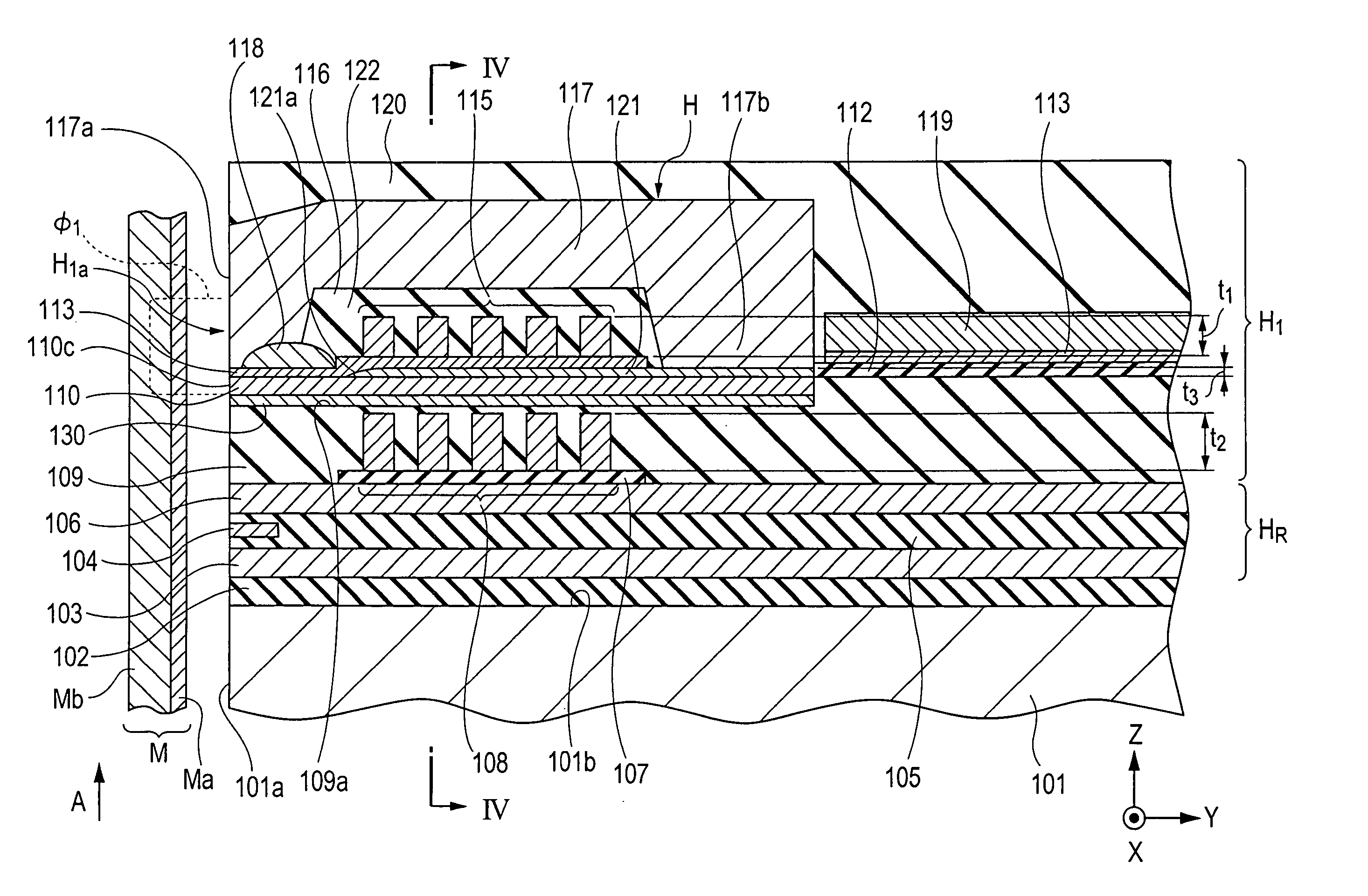
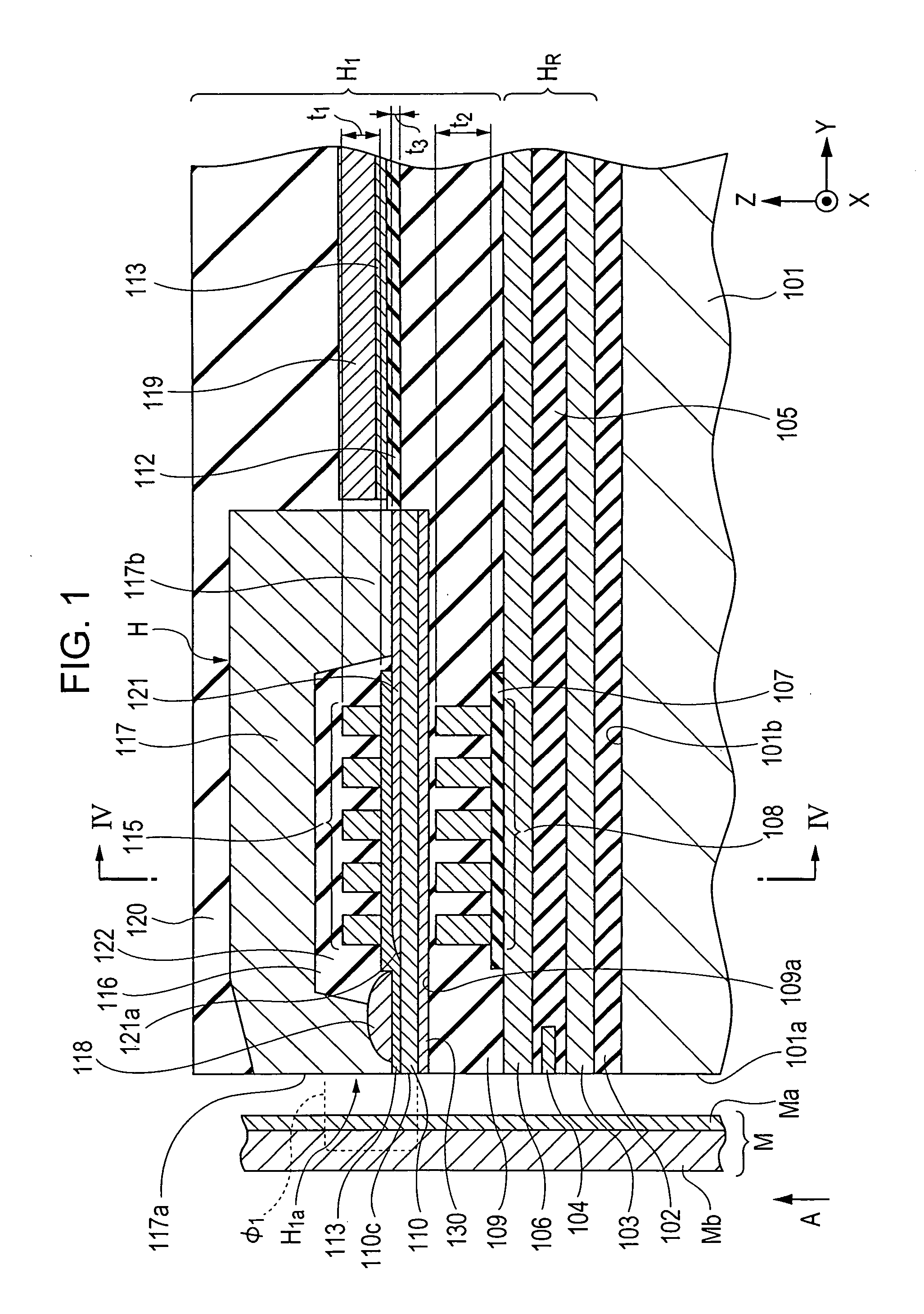
[0058]FIG. 1 is a vertical cross-sectional view of a magnetic head according to the present invention.

[0059] A magnetic head H1 shown in FIG. 1 is a so-called perpendicular magnetic recording head which applies a perpendicular magnetic field to a recording medium M so as to magnetize a hard film Ma of the recording medium M in a perpendicular direction.

[0060] The recording medium M has, for example, a disc shape, is composed of the hard film Ma having a high residual magnetization and located at a magnetic head H1 side and a soft film Mb having a high magnetic permeability and located at a side apart from the magnetic head H1, and is allowed to rotate around the center of the disc.

[0061] A slider 101 is formed of a non-magnetic material such as Al2O3.TiC, and a facing surface 101a of the slider 101 faces the recording medium M. When the recording medium M is allowed to rotate, due to an airflow generated along the surface thereof, the slider 101 floats above the surface of the rec...

second embodiment

[0092]FIG. 5 is a vertical cross-sectional view of a magnetic head according to the present invention.

[0093] The magnetic head of this embodiment is equivalent to the magnetic head shown in FIGS. 1 to 3 except that the auxiliary yoke layer 121 formed by sputtering is in contact with the bottom surface of the main magnetic pole layer 110.

[0094] Also in the magnetic head of this embodiment, the film thickness t2 of the second coil layers (second coil pieces) 108 disposed under the main magnetic pole layer (first magnetic layer) 110 is larger than the film thickness t1 of the first coil layers (first coil pieces) 115.

[0095] Accordingly, while the magnetic path length of magnetic flux flowing through the main magnetic pole layer (first magnetic layer) 110 and the return path layer (second magnetic layer) 117 is decreased by decreasing the film thickness t1 of the first coil layers (first coil pieces) 115 disposed in the space 122 between the main magnetic pole layer (first magnetic la...

third embodiment

[0096]FIG. 6 is a vertical cross-sectional view of a magnetic head according to the present invention.

[0097] The magnetic head of this embodiment is equivalent to the magnetic head shown in FIGS. 1 to 3 except that the auxiliary yoke layer 121 formed by plating is in contact with the bottom surface of the main magnetic pole layer 110.

[0098] Also in the magnetic head of this embodiment, the film thickness t2 of the second coil layers (second coil pieces) 108 disposed under the main magnetic pole layer (first magnetic layer) 110 is larger than the film thickness t1 of the first coil layers (first coil pieces) 115.

[0099] Accordingly, while the magnetic path length of magnetic flux flowing through the main magnetic pole layer (first magnetic layer) 110 and the return path layer (second magnetic layer) 117 is decreased by decreasing the film thickness t1 of the first coil layers (first coil piece) 115 disposed in the space 122 between the main magnetic pole layer (first magnetic layer)...


PUM

PropertyMeasurementUnit
length L2aaaaaaaaaa
length L3aaaaaaaaaa
thickness t3aaaaaaaaaa

Abstract

A magnetic head includes first and second magnetic layers and first and second coil pieces in a space between and outside the first and second magnetic layers, respectively. A film thickness of second coil layers (second coil pieces) disposed below a main magnetic pole layer (first magnetic layer) is larger than a film thickness of first coil layers (first coil pieces). Hence, while a magnetic path length of magnetic flux flowing through the main magnetic pole layer (first magnetic layer) and a return path layer (second magnetic layer) is decreased by decreasing the film thickness of the first coil layers (first coil pieces) disposed in a space between the main magnetic pole layer (first magnetic layer) and the return path layer (second magnetic layer), series resistance of an entire coil layer can be decreased by increasing the film thickness of the second coil layers (second coil pieces).

Description

BACKGROUND OF THE INVENTION [0001] 1. Field of the Invention [0002] The present invention relates to a recording magnetic head used as a floating type magnetic head or the like, and more particularly, relates to a magnetic head capable of reducing series resistance of a coil layer. [0003] 2. Description of the Related Art [0004]FIG. 19 is a vertical cross-sectional view showing a related magnetic head. [0005] A magnetic head H1 shown in FIG. 19 is a so-called perpendicular magnetic recording head which applies a perpendicular magnetic field to a recording medium M so as to magnetize a hard film Ma of the recording medium M in a perpendicular direction. [0006] The recording medium M has, for example, a disc shape, is composed of the hard film Ma having a high residual magnetization and located at a magnetic head H1 side and a soft film Mb having a high magnetic permeability and located at a side apart from the magnetic head H1, and is allowed to rotate around the center of the disc. ...

Claims


Application Information

Patent Timeline
Patent Type & Authority Applications(United States)
IPC IPC(8): G11B5/147
CPCG11B5/1278
Inventor KOBAYASHI, KIYOSHI
Owner TDK CORPARATION
Why Eureka
Try Eureka