Helically fluted tubular fuel rod support

a technology of fuel rods and supports, applied in the direction of nuclear elements, nuclear engineering problems, greenhouse gas reduction, etc., can solve the problems of restricting the flow of water, and achieve the effect of reducing the pressur

Active Publication Date: 2006-07-13
WESTINGHOUSE ELECTRIC CORP
View PDF26 Cites 69 Cited by
  • Summary
  • Abstract
  • Description
  • Claims
  • Application Information

AI Technical Summary

Benefits of technology

[0014] In a preferred embodiment, the tubular member has a wall of uniform thickness so that the helical fuel rod contact portion defines a passage with a helical shape on both the side adjacent to the fuel rod and the side adjacent to the cell wall. These helical shaped passages act to mix the water so that mixing vanes are not required. There are at least two advantages to using the helical shaped passages; first, the water flow does not impinge on the shaped passage, so there is a minimal pressure drop created by the mixing structure. Second, by reversing the direction of the helical passage in selected cells, the amount of torque exerted on the frame assembly may be controlled.

Problems solved by technology

However, given the relatively short height of a typical cell, the pitch (radial distance / height) of the helical fuel rod contact portion may be too great thereby restricting the flow of water through the helical portion of the passage.

Method used


Image

  • Helically fluted tubular fuel rod support
  • Helically fluted tubular fuel rod support
  • Helically fluted tubular fuel rod support

Examples


Embodiment Construction

[0035] As used herein, directional terms, such as, but not limited to, “upper” and “lower” relate to the components as shown in the Figures and are not limiting upon the claims.

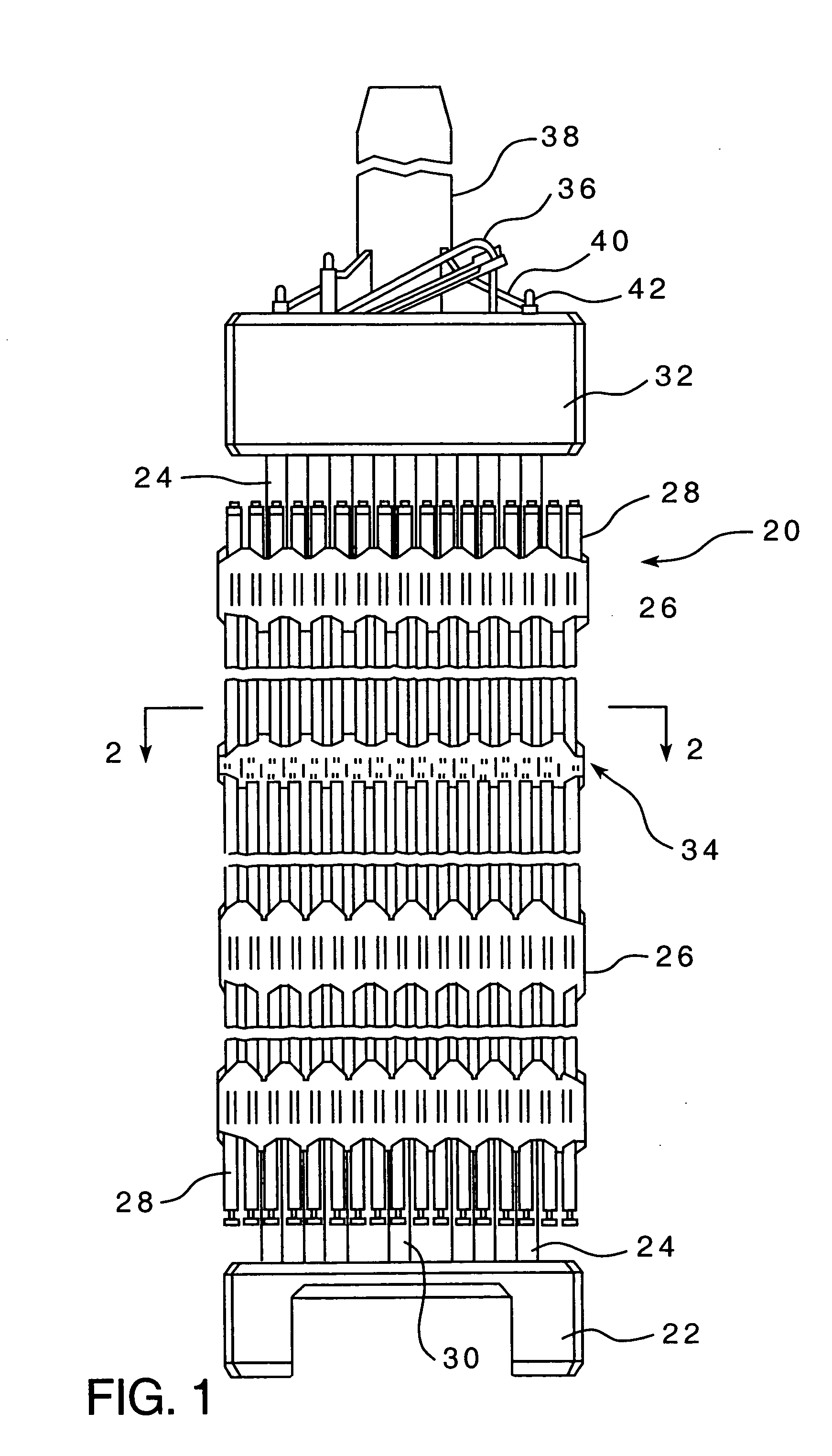
[0036] As shown in FIG. 1, there is a fuel assembly 20 for a nuclear reactor. The fuel assembly 20 is disposed in a water vessel (not shown) having an inlet at the bottom and an outlet at the top. The fuel assembly 20 comprises a lower end structure or bottom nozzle 22 for supporting the fuel assembly 20 on the lower core plate (not shown) in the core region of a reactor (not shown); a number of longitudinally extending control rod guide tubes, or thimbles 24, projecting upwardly from the bottom nozzle 22; a plurality of transverse support grids 26 axially spaced along the guide thimbles 24; an organized array of elongated fuel rods 28 transversely spaced and supported by the grids 26; an instrumentation tube 30 located in the center of the assembly; and an upper end structure or top nozzle 32 attached to th...


PUM


Abstract

A support grid for a nuclear fuel assembly, the fuel rod assembly having a generally cylindrical fuel rod with a diameter, wherein the support grid includes a frame assembly having a plurality of generally uniform cells, each the cell having at least one wall and a width and at least one generally cylindrical tubular member having a cell contact portion with a greater diameter and at least one helical fuel rod contact portion with a lesser diameter, the cell contact portion and the fuel rod contact portion joined by a transition portion, the greater diameter being generally equivalent to the cell width, and the lesser diameter being generally equivalent to the fuel rod diameter such that a fuel rod disposed in the tubular member would engage the inner diameter. Wherein the least one tubular member disposed in one cell of the plurality of generally square cells so that the cell contact portion engages the at least one cell sidewall.

Description

BACKGROUND OF THE INVENTION [0001] 1. Field of the Invention [0002] The present invention relates to nuclear reactor fuel assemblies and more particularly to an array for supporting fuel rods wherein the array, or support assembly, consists of a matrix of substantially flat members forming a grid-like frame assembly and a plurality of helically fluted tubular members. [0003] 2. Background Information [0004] In a typical pressurized water reactor (PWR), the reactor core is comprised of a large number of generally vertically, elongated fuel assemblies. The fuel assemblies include a support grid structured to support a plurality of fuel rods. The fuel assembly includes a top nozzle, a bottom nozzle, a plurality of the support grids and intermediate flow mixing grids, and a plurality of thimble tubes. The support grids are attached to the plurality of elongated thimble tubes which extend vertically between the top and bottom nozzles. The thimble tubes typically receive control rods, plu...

Claims


Application Information

Patent Timeline
Patent Type & Authority Applications(United States)
IPC IPC(8): G21C3/34
CPCG21C3/344G21C3/352G21C3/356G21Y2002/201G21Y2002/302G21Y2002/303G21Y2004/30Y02E30/40Y02E30/30
Inventor JIANG XIAOYAN (JANE)
Owner WESTINGHOUSE ELECTRIC CORP
Why Eureka
Try Eureka