Mat for mounting a pollution control element in a pollution control device for the treatment of exhaust gas

a technology of pollution control device and pollution control element, which is applied in the direction of machines/engines, lighting and heating apparatus, separation processes, etc., can solve the problems of high cost of polycrystalline fibers, increased gap between the inside peripheral wall of the housing and the outer wall of the monolith, and increased fragility of the ceramic pollution control monolith

Inactive Publication Date: 2006-07-13
3M INNOVATIVE PROPERTIES CO
View PDF15 Cites 40 Cited by
  • Summary
  • Abstract
  • Description
  • Claims
  • Application Information

AI Technical Summary

Benefits of technology

[0013] According to a particular aspect, there is provided a mat for mounting a pollution control element (e.g., a diesel pollution control monolith) in a housing (e.g., a metallic casing) of a pollution control device, the mat being a non-intumescent mat comprising at least 90% by weight based on the total weight of the mat of chopped magnesium aluminium silicate glass fibers that have a number average diameter of 5 μm or more and a length of 0.5 to 15 cm, the glass fibers being needle punched or stitch bonded, the mat being free or substantially free of organic binder and being comprised of at least two layers of the chopped magnesium aluminium silicate glass fibers, wherein the two layers are differing in their glass fiber composition. A mat according to this aspect was found to be particularly suitable for optimizing performance and manufacturing cost of a mounting mat for pollution control devices for diesel engine exhaust.

Problems solved by technology

The monoliths and in particular the ceramic pollution control monoliths, used in pollution control devices are fragile and susceptible to vibration or shock damage and breakage.
This means that as the pollution control device is heated the gap between the inside peripheral wall of the housing and the outer wall of the monolith increases.
Such thermal cycling occurs hundreds of times during the life and use of the pollution control device.
Polycrystalline fibers are much more expensive than normal, melt formed ceramic fibers and, therefore, mats using these fibers are only used where absolutely necessary as, for example, with ultra thin-wall monoliths.
Because of extremely low exhaust gas temperature, mounting of DOC's with conventional mounting materials has been problematic.
Additionally, this temperature is too low to burn out the organic binder contained in intumescent mat materials.
At these temperatures the binder only softens, which acts to interfere with the resiliency of the ceramic fibers.
As a result, field failures have occurred with DOC's when using conventional intumescent mounting mats.
This is expensive and time consuming.
Auxiliary wire mesh “L” seals have also been employed to augment the holding force of intumescent mats at low temperature, but also add cost and complexity to assembly.
Most non-intumescent mats while performing somewhat better still contain an organic binder, which significantly reduces the resiliency of the fibers in the 200-300° C. temperature range.
Moreover, it was found that the mounting mats disclosed in this U.S. patent, still do not adequately perform for treatment of exhaust from diesel engines, in particular TDI engines.

Method used


Image

  • Mat for mounting a pollution control element in a pollution control device for the treatment of exhaust gas
  • Mat for mounting a pollution control element in a pollution control device for the treatment of exhaust gas

Examples


example 1

[0071] 40 liters of S-2 glass fibers of approximately 9 μm in average diameter and 2.54 cm in length were obtained from Advanced Glassfiber Yarns LLC (AGY). The fibers were essentially shot free.

[0072] The glass fibers were opened in a two-zone Laroche opener. The first zone had a feed speed of 2 m / min and a Lickerin roll speed of 2,500 rev / min. The second zone had a feed speed of 4 m / min and a Lickerin roll speed of 2,500 rev / min. The output speed was 6.5 m / min.

[0073] The opened fibers were then fed into a conventional web-forming machine (commercially available under the trade designation “Rando Webber” from Rando Machine Corp. of Macedon, N.Y., wherein the fibers were blown onto a porous metal roll to form a continuous web. The continuous web was then needle-bonded on a conventional needle tacker. The needle speed was 100 cycles / min and the output speed was 1.1 m / min. The “weight per area” of the mounting mat could be adjusted as desired. In tests where the value of “weight per...

example 2

[0076] Example 2 was prepared by the method described in Example 1 with the exception that E-glass fibers (chopped glass strands, diameter 9 μm, chopped to a length of 1 inch (25.4 mm) available from Advanced Glassfiber Yarns LLC (AGY), Aiken, S.C., USA) were employed. The composition of the mat of Example 2 is summarized in Table 1.

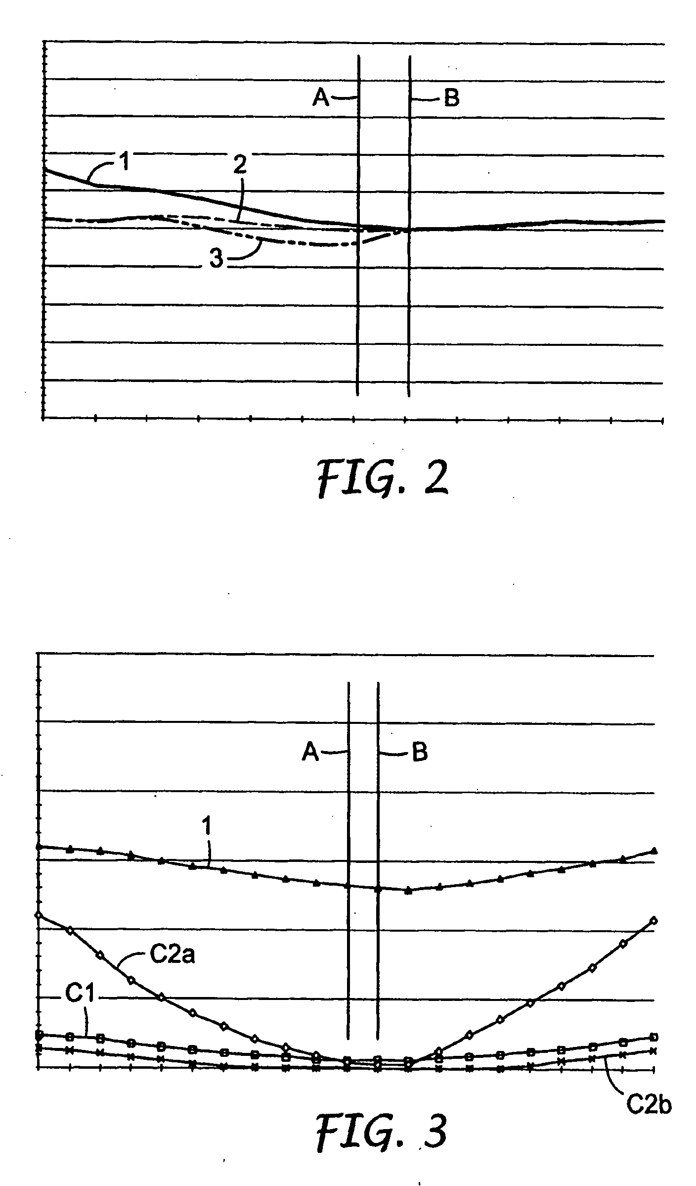
[0077] Tests on the mat of Example 2 include the Cyclical Compression Test. Results are summarized in Table 3 and show that at diesel pollution control device temperatures (i.e., average mat temperature of 250° C.), the mat keeps 86.3% of its original pressure after 1000 compression cycles.

[0078] Example 2 was also tested in the RCFT using the same conditions as used in Example 1. Example 2 maintained adequate holding force over the entire temperature range.

example 3

[0079] R-glass fibers (60% SiO2, 25% Al2O3, 9% CaO, and 6% MgO) having a diameter of ca. 10 μm, chopped to a length of 36 mm, obtained from Saint-Gobain Vetrotex, were processed into a web by the method described in Example 1. The composition of the mat of Example 4 is summarized in Table 1.

[0080] Tests on the R-glass mat of Example 3 include the Cyclical Compression Test. Results are summarized in Table 3 below and show that at diesel pollution control device temperatures (i.e., average mat temperature of 250° C.), the mat keeps 95.5% of its original pressure after 1000 compression cycles.

[0081] Additionally, an RCFT test was performed on the mat of Example 3 in the same way as for the mat of Example 1 except that the simulated temperature range for the monolith was from 25° C. to 500° C. and 25 to 200° C. for the skin. Example 3 maintained adequate holding force over the entire temperature range.


PUM

PropertyMeasurementUnit
densityaaaaaaaaaa
densityaaaaaaaaaa
lengthaaaaaaaaaa

Abstract

A pollution control device suitable for use with an internal combustion engine (e.g., a diesel engine) and comprising a pollution control element arranged in a casing with non-woven mat disposed between the casing and the pollution control element, said non-woven mat being a non-intumescent mat comprising at least 90% by weight based on the total weight of the mat of chopped magnesium aluminium silicate glass fibers that have a number average diameter of 5μ or more and a length of 0.5 to 15 cm, said glass fibers being needle punched or stitch bonded and said mat being free or substantially free of organic binder.

Description

FIELD OF THE INVENTION [0001] The present invention relates to pollution control devices that include a mounting mat for mounting a pollution control element in the pollution control device. In particular, the invention relates to pollution control devices that are intended for the treatment of the exhaust of an internal combustion engine (e.g., a diesel engine). The mounting mat of the pollution control device can be designed so that it is particularly suited for lower temperature applications such as diesel catalytic converters or other pollution control elements adapted for reducing pollution from the exhaust of diesel engines. BACKGROUND OF THE INVENTION [0002] Diesel pollution control devices include catalytic converters and diesel particulate filters or traps. The pollution control devices typically comprise a metal housing or casing with a pollution control element securely mounted within the casing by a resilient and flexible mounting mat. Pollution control devices are unive...

Claims


Application Information

Patent Timeline
Patent Type & Authority Applications(United States)
IPC IPC(8): B01D53/34
CPCD04H1/42D04H1/46D04H1/52D04H13/008F01N3/2853F01N3/2864F01N2310/02D04H1/4209D04H1/4218D04H1/4374D04H1/43835D04H1/43838
Inventor MERRY, RICHARD P.KUNZE, ULRICH E.SWAN, MICHAEL D.
Owner 3M INNOVATIVE PROPERTIES CO
Why Eureka
Try Eureka