Glass tube, method of manufacturing the glass tube, and method of adhering the glass tube
a glass tube and manufacturing method technology, applied in the field of glass tubes, can solve the problems of glass tube not being bonded, glass tube softening by heating spread on the panel, glass tube softening cannot be achieved, etc., and achieve good bonding
- Summary
- Abstract
- Description
- Claims
- Application Information
AI Technical Summary
Benefits of technology
Problems solved by technology
Method used
Image

Examples
embodiment 1
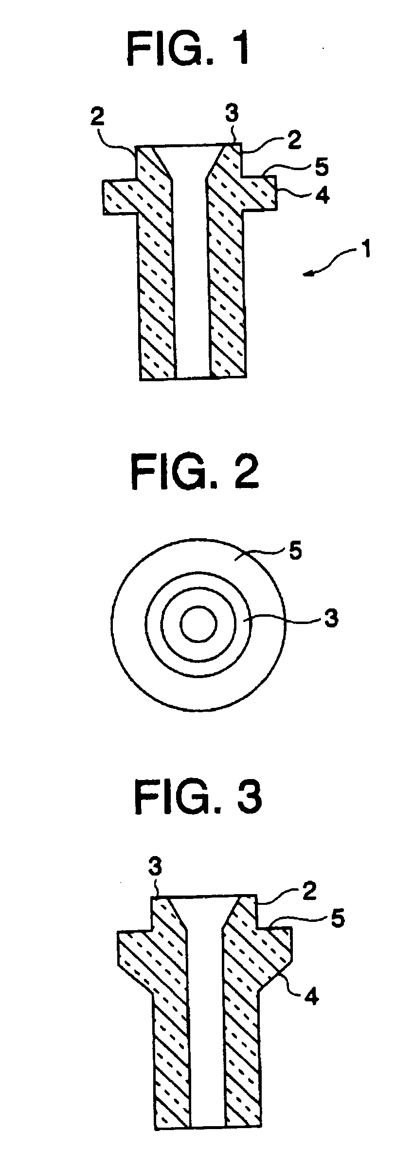
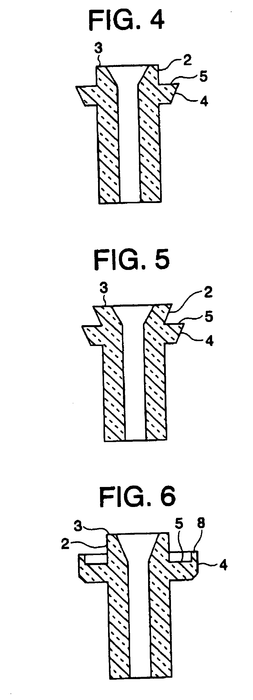
[0054] A glass tube 1 of the present invention will be described with reference to FIG. 1 to FIG. 10.
[0055]FIG. 1 shows an example (a cross section) of the glass tube 1 of the present invention, which is formed by using a straight tube that is formed of soda-lime glass having the aforesaid glass composition by using a Danner process or the like, and a flange portion face 5 is worked into a planar shape, the outside diameter of a tube end portion 2 is made equal to the diameter of the straight tube, and the inside diameter thereof is fanned out. Note that a coefficient of thermal expansion of the glass tube 1 used here is 84×10−7 / ° C. and a softening point thereof is 725° C.
[0056] When seen from a direction of an end face 3 of the glass tube, the flange portion face 5 in FIG. 1 has a shape such that the straight tube is positioned at the center of a circular flange portion 4 as shown in FIG. 2. The flange portion 4 is thus continuously formed around an outer periphery of the straig...
embodiment 2
[0061] A preferable frit glass integrated glass tube of the present invention is formed by joining a frit glass 6 to a glass tube 1 on a ceramic substrate, and therefore, this manufacturing method will be described below. Note that physical characteristics such as a coefficient of thermal expansion and a softening point of the glass tube 1 used here are the same as those in the above-described embodiment 1.
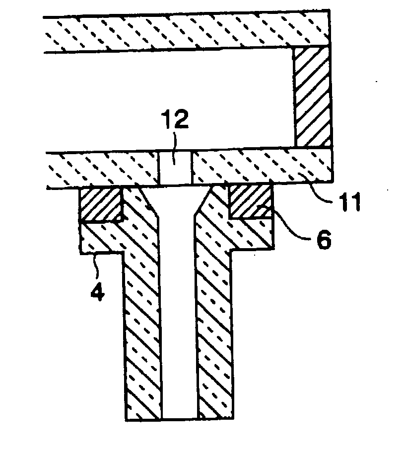
[0062] First, the frit glass 6 formed in a ring shape on the ceramic substrate and the glass tube 1 are set at predetermined positions, the temperature thereof is raised to a level not high enough for the frit glass 6 to greatly change in its shape, the temperature is kept in this state for about 10 minutes to join the frit glass 6 to a flange portion face 5 of the glass tube 1 and an outer peripheral face of a tube end portion 2, and next, the temperature is lowered to a room temperature, whereby the frit glass integrated glass tube of the present invention is obtained (see FIG....
embodiment 3
[0065] Here, a bonding method when a frit glass integrated glass tube of the present invention is set horizontal or upside down to be bonded to a panel will be shown. Note that a coefficient of thermal expansion of a panel glass used here was 83×10−7 / ° C. and a softening point thereof was 830° C., and a glass tube used here had the same physical characteristics as those in the Embodiments 1, 2 described above.
[0066] When the frit glass integrated glass tube is placed on the panel to be bonded to the panel by temperature rise as has been conventionally practiced, it is possible to bond the glass tube 1 if only the frit glass 6 is melted by the temperature rise. However, when the glass tube 1 is set horizontal or upside down, unless bonding conditions of the frit glass 6 are controlled, the frit glass 6 drips down even if a face to which the frit glass 6 is joined is made larger in the glass tube 1, and therefore, it is not possible to bond the glass tube 1. FIG. 15 shows a conceptua...
PUM
| Property | Measurement | Unit |
|---|---|---|
| Fraction | aaaaa | aaaaa |
| Shape | aaaaa | aaaaa |
Abstract
Description
Claims
Application Information
 - R&D
- Intellectual Property
- Life Sciences
- Materials
- Tech Scout
- Unparalleled Data Quality
- Higher Quality Content
- 60% Fewer Hallucinations
Browse by: Latest US Patents, China's latest patents, Technical Efficacy Thesaurus, Application Domain, Technology Topic, Popular Technical Reports.
© 2025 PatSnap. All rights reserved.Legal|Privacy policy|Modern Slavery Act Transparency Statement|Sitemap|About US| Contact US: help@patsnap.com