Structured electrolyte for micro-battery

a micro-battery and electrolyte technology, applied in the field of structured electrolyte for micro-batteries, can solve the problems of poor power performance, difficult to reach a high height-to-width ratio of cavities, and inability to achieve a regular and homogeneous coating of lateral (vertical) and base walls for cavities too deep and narrow

Inactive Publication Date: 2006-07-13
COMMISSARIAT A LENERGIE ATOMIQUE ET AUX ENERGIES ALTERNATIVES
View PDF8 Cites 117 Cited by
  • Summary
  • Abstract
  • Description
  • Claims
  • Application Information

AI Technical Summary

Problems solved by technology

However, the higher resistance linked to the diffusion of lithium throughout the material leads to poorer power performance.
Nevertheless, with such a system, it is difficult to reach a high height to width

Method used


Image

  • Structured electrolyte for micro-battery
  • Structured electrolyte for micro-battery
  • Structured electrolyte for micro-battery

Examples


Embodiment Construction

[0010] The aim of the invention is to overcome the problems linked to the prior art with regard to the storage capacity and the power of the energy supply.

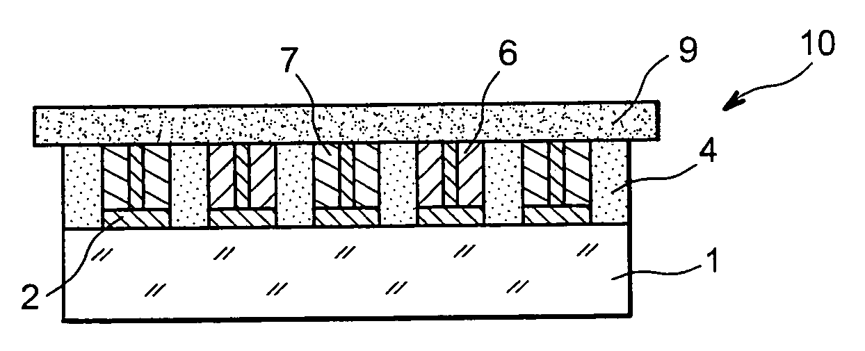
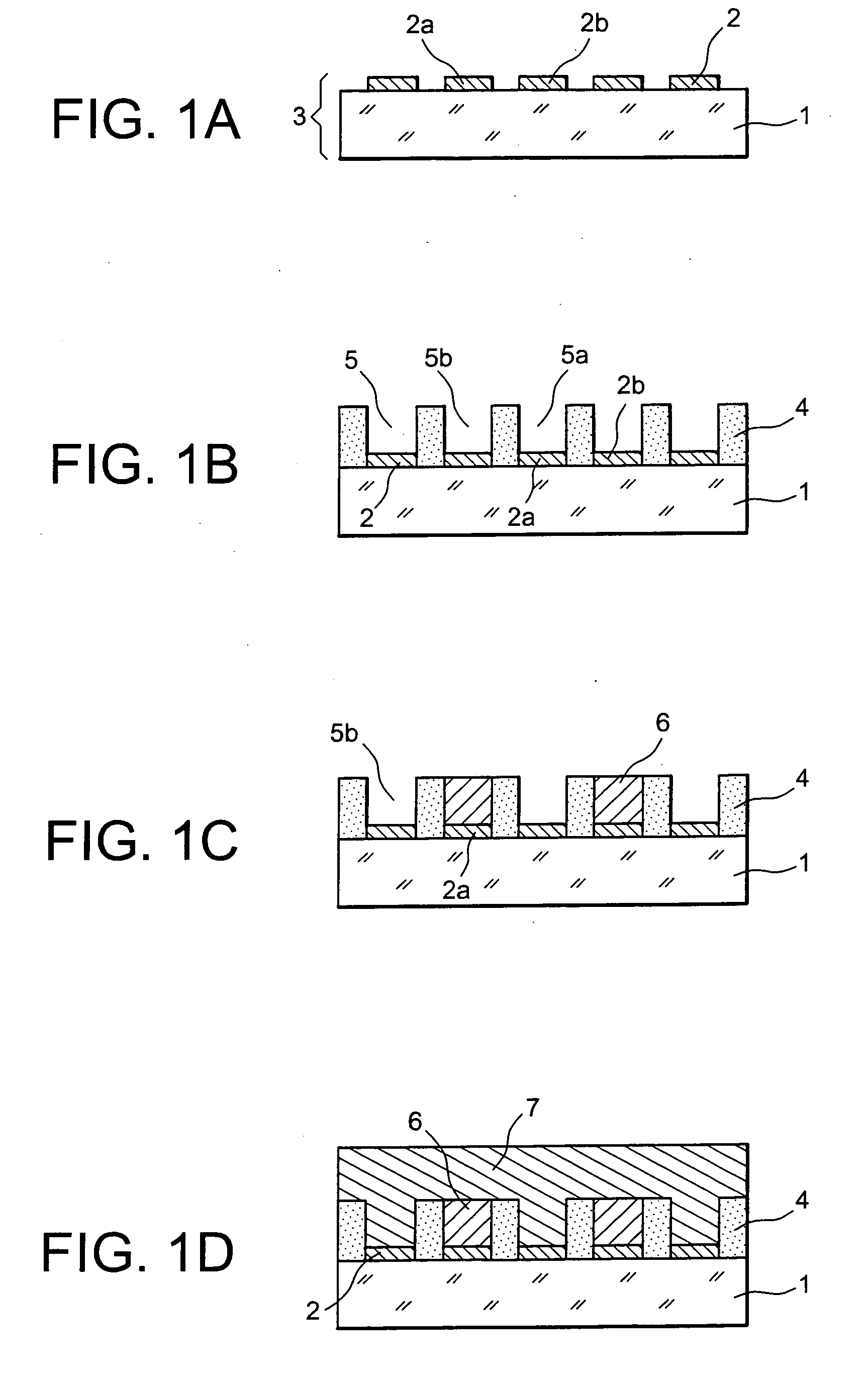
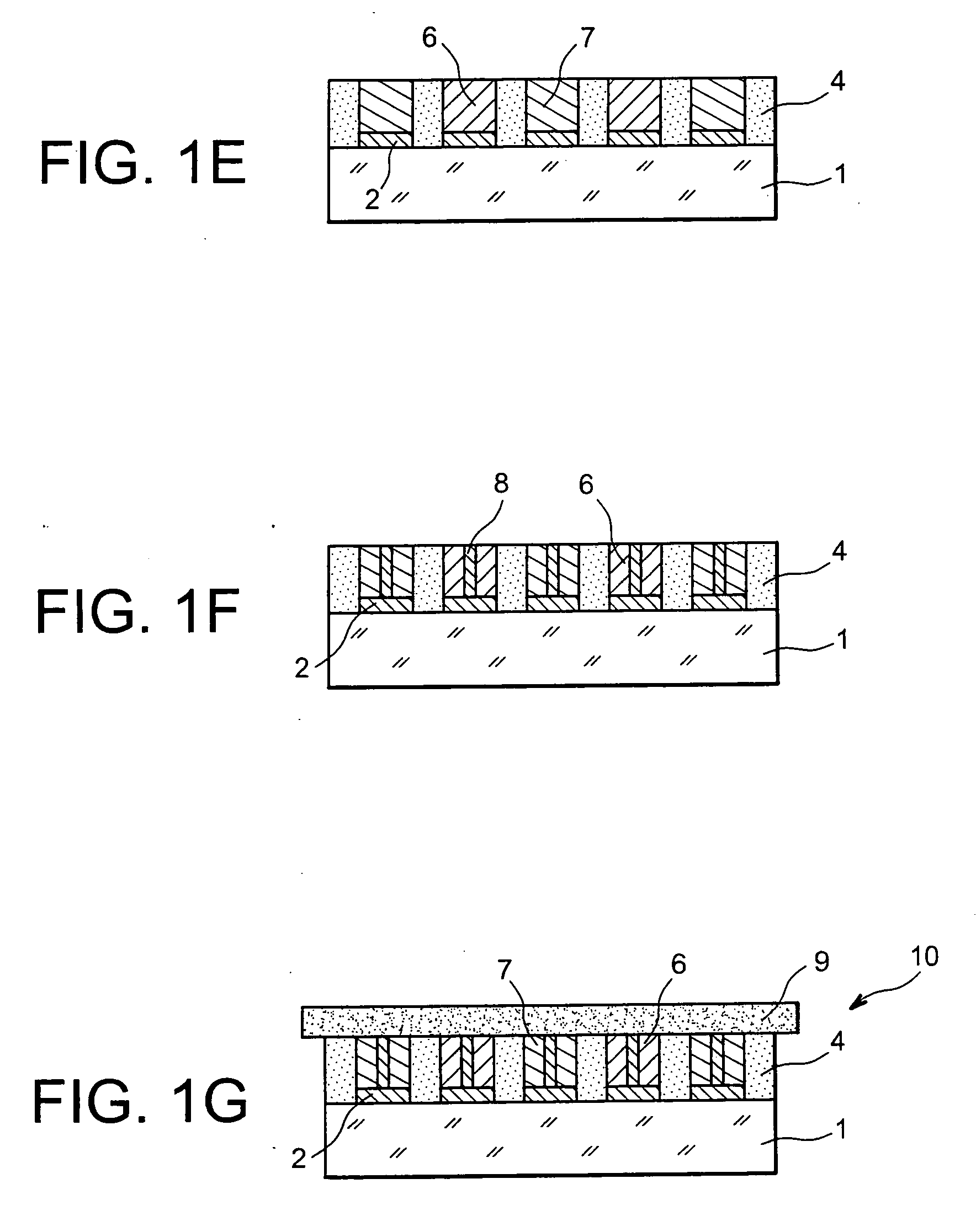
[0011] More specifically, the invention recommends the use of a structured electrolyte in an energy storage device. The layer of electrolyte, deposited flat by conventional techniques, is then machined in such a way as to include cavities crossing through it: said cavities are intended to receive the electrode materials. Thus, the ion exchange surface is increased, whereas the general size of the battery may remain similar and thereby as minimal as possible.

[0012] According to one of its aspects, the invention concerns a method for manufacturing a micro-battery comprising the creation of cavities in a layer of electrolyte and the filling of said cavities by a cathode and / or anode material. The filling of the cavities may be selective between anode and cathode, or it is possible to create the cavities in two steps and to fill the...


PUM

PropertyMeasurementUnit
Ratioaaaaaaaaaa
Levelaaaaaaaaaa

Abstract

In order to increase the capacity of an “all-solid” type micro-battery, the layer of electrolyte is structured: transversing cavities are created in the flat layer, advantageously at the level of patches of collector material, then filled by anode or cathode material.

Description

TECHNICAL FIELD [0001] The invention relates to the field of energy storage devices and principally micro-batteries manufactured in thin films by vacuum deposition techniques. [0002] More specifically, the invention concerns a structuring of the electrolyte that makes it possible to increase the capacity of a battery by increasing the ion exchange surface of the electrodes. The invention further concerns a method enabling the manufacture of said micro-battery. BACKGROUND ART [0003] Among energy storage devices, some particularly used micro-batteries, known as “all-solid”, are in the form of films: all of the components of the micro-battery, in other words the current collectors, the positive and negative electrodes, the electrolyte, and even the encapsulation, are thin films, obtained by deposition, principally by physical vapour deposition (PVD) or chemical vapour deposition (CVD). The techniques used enable objects of any shape to be formed. [0004] As usual, the operating principl...

Claims


Application Information

Patent Timeline
IPC IPC(8): H01M2/02H01M4/58H01M10/04H01M4/04H01M10/052H01M10/0562H01M10/0585H01M10/36
CPCH01M4/0423H01M4/0428H01M6/40H01M10/0436H01M10/052Y10T29/49115H01M10/0585H01M2300/0068H01M2300/0094Y02E60/122H01M10/0562Y02E60/10Y02P70/50
Inventor SALOT, RAPHAELGAILLARD, FREDERICDANEL, JEAN-SEBASTIENLAURENT, JEAN-YVES
Owner COMMISSARIAT A LENERGIE ATOMIQUE ET AUX ENERGIES ALTERNATIVES
Why Eureka
Try Eureka