
New-type Ni-MH power battery

a power battery, new type technology, applied in the direction of cell components, final product manufacturing, sustainable manufacturing/processing, etc., can solve the problems of inability to bear a high current, high cost, complicated manufacturing process, etc., to achieve low cost, simple manufacturing process, and favorable current collecting effect

Inactive Publication Date: 2006-07-13
SHENZHEN GREPOW BATTERY CO LTD
View PDF2 Cites 8 Cited by
  • Summary
  • Abstract
  • Description
  • Claims
  • Application Information

AI Technical Summary

Benefits of technology

The present invention provides a new-type Ni-MH power battery with favorable current collecting effects and easy high-current discharge. The battery has large capacity, high power / volume ratio, and low manufacturing cost. The technical effects of the invention include designing a new electrode assembly with two or more welding spots between the negative electrode current collector and the metal can, using a metal foam conductor between the negative electrode and the negative electrode current collector, and using a metal mesh or punched metal strip as the substrate of the negative electrode plate. The invention also omits seam-welded nickel sheets and binding wires or adhesive tapes on the outer layer of the electrode assembly.

Problems solved by technology

A Ni-MH power battery of such structure has the shortcomings of high cost due to that it consumes a lot of expensive nickel material, and has a complicated manufacturing process.
The negative electrode current collector contacts the metal can only via one welding spot, so it cannot bear a high current.
The adhesive tape is bound on the outer layer of the electrode assembly, taking up a certain space, thus resulting in small capacity, low power / volume ratio, and low energy / volume ratio of the battery.

Method used


Image

  • New-type Ni-MH power battery
  • New-type Ni-MH power battery
  • New-type Ni-MH power battery

Examples


Embodiment Construction

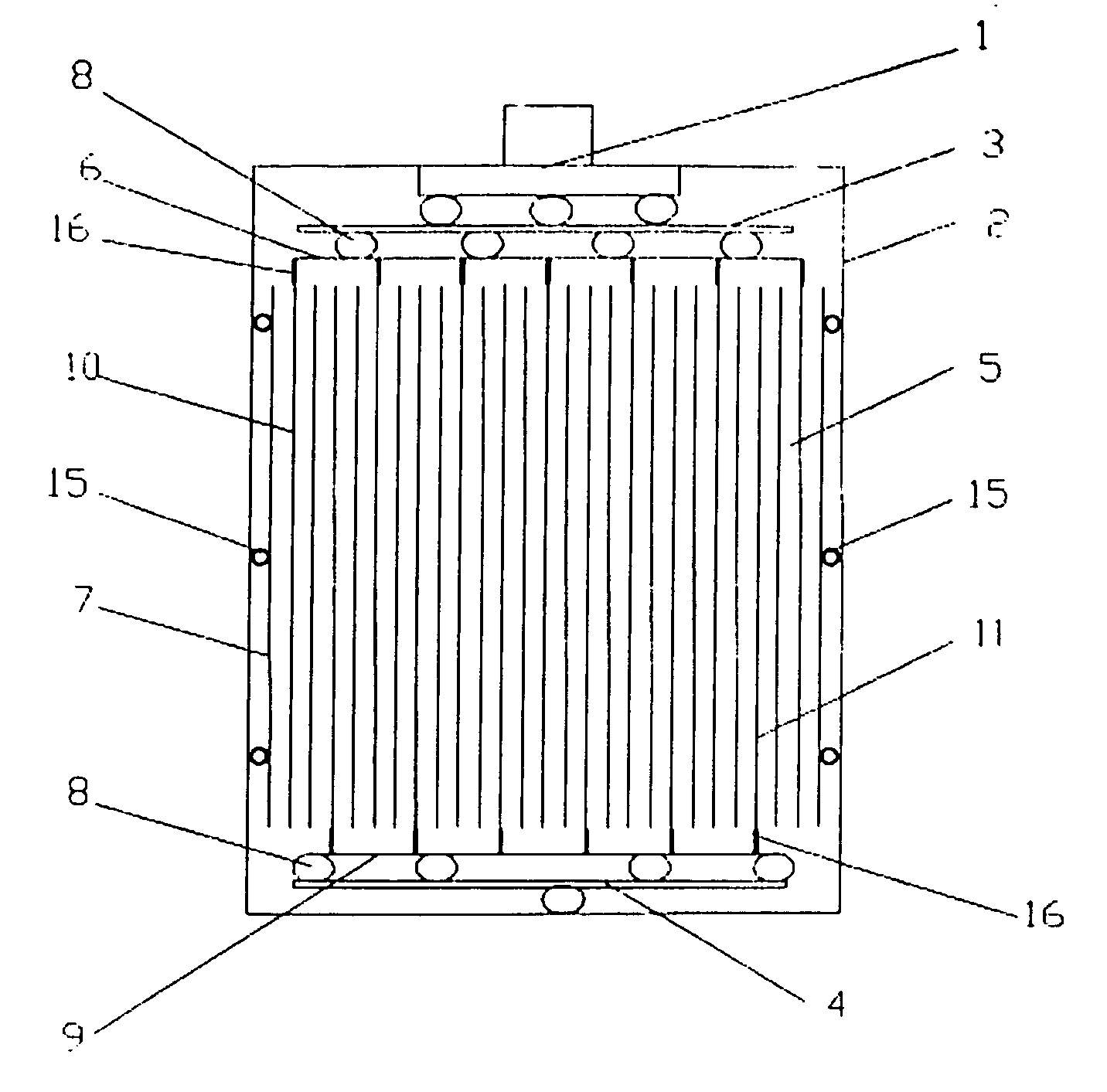
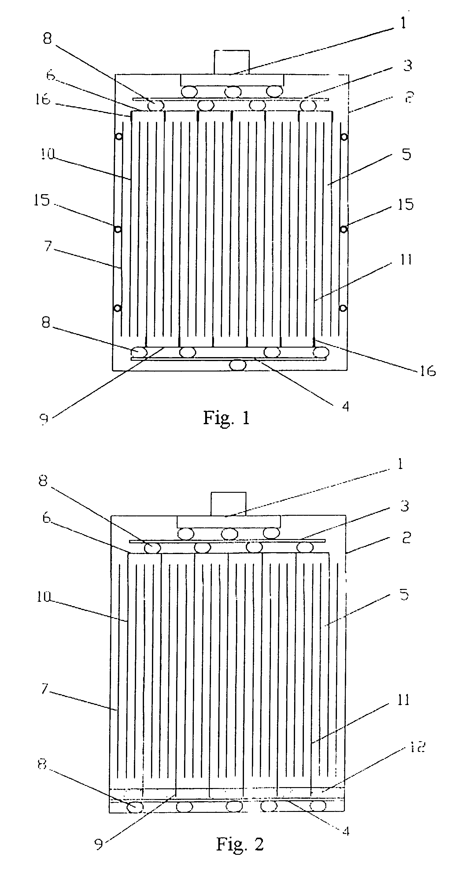
[0018] Referring to FIG. 2, a schematic sectional view of a new-type Ni-MH power battery is illustrated. As shown in the figure, the new-type Ni-MH power battery includes a battery vent cap 1, a can 2, positive electrode and negative electrode current collector 3, 4 inside the can 2, and an electrode assembly 5 formed by winding a positive electrode plate 10, a separator 7, a negative electrode plate 11 having a copper mesh as the substrate. The upper and lower surfaces of the positive electrode current collector 3 are connected to the lower surface of the battery vent cap 1 and a positive electrode 6 of the electrode assembly 5 via welding spots 8 respectively. A negative electrode 9 of the electrode assembly 5 is embedded in a metal foam conductor 12. The upper surface of the negative electrode current collector 4 is connected to the metal foam, while the lower surface of the negative electrode current collector 4 is connected to the inner surface of the can 2 via several welding ...


PUM

PropertyMeasurementUnit
widthaaaaaaaaaa
currentaaaaaaaaaa
power/volume ratioaaaaaaaaaa

Abstract

The present invention provides a new-type Ni-MH power battery, which includes a battery vent cap 1, a metal can 2, a positive electrode current collector 3 and a negative electrode current collector 4 inside the can 2, and an electrode assembly 5 generally formed by winding a positive electrode plate 10, a separator 7, and a negative electrode plate 11 having a copper mesh as a substrate. The upper and lower surface of the positive electrode current collector 3 are connected to the lower surface of the battery vent cap 1 and a positive electrode 6 of the electrode assembly 5 via welding spots 8 respectively. The lower surface of the negative electrode current collector 4 is connected to the inner surface of the can 2 via multiple welding spots 8. The upper surface of the negative electrode current collector 4 contacts a negative electrode 9 of the electrode assembly via a layer of metal foam conductor 12, in which the negative electrode 9 is embedded in the metal foam conductor 12. The invention is beneficial to high-current discharge, and has favorable current collecting effect, low cost, large capacity, high power / volume ratio, high energy / volume ratio, and outstanding comprehensive battery performance.

Description

BACKGROUND OF THE PRESENT INVENTION [0001] 1. Field of Invention [0002] The present invention relates to a rechargeable Ni-MH battery, and more particularly to a Ni-MH power battery. [0003] 2. Description of Related Arts [0004] Electric vehicles are widely accepted because of the advantages of no exhaust emission, low noise, and being friendly to environment, and have considerable development prospects. Ni-MH power batteries providing power to electric vehicles have attracted great attention due to the advantages of outstanding comprehensive performance, capability of satisfying high power start-up required by electric vehicles, wide operating temperature range, recharge ability without memory effect, and no heavy metals such as cadmium and lead exhausted. [0005] Conventional Ni-MH battery has a battery vent cap 1, a metal can 2, positive electrode and negative electrode current collector 3, 4 inside the can 2, and an electrode assembly 5 formed by winding a positive electrode plate...

Claims


Application Information

Patent Timeline
Patent Type & Authority Applications(United States)
IPC IPC(8): H01M2/26H01M4/74H01M4/66H01M50/533H01M50/536
CPCH01M2/266H01M4/661H01M4/74H01M6/10H01M10/345Y02E60/124Y02E60/10Y02P70/50H01M50/536H01M50/533
Inventor XU, ZICHUNFAN, ZHENGGANG
Owner SHENZHEN GREPOW BATTERY CO LTD
Learn More