Current collector and lithium ion battery containing current collector

A current collector and organic technology, applied in the direction of battery electrodes, secondary batteries, electrode carriers/current collectors, etc., can solve problems such as poor product consistency, breakage, broken edges, burrs, battery short circuits, etc., to improve conductivity and concentration Effect of flow, increase of volume energy density, effect of increase of mass energy density

Active Publication Date: 2020-06-12
荆门市诺维英新材料科技有限公司
View PDF5 Cites 6 Cited by
  • Summary
  • Abstract
  • Description
  • Claims
  • Application Information

AI Technical Summary

Problems solved by technology

[0003] Existing current collectors are generally made of aluminum foil or copper foil materials, which can meet the manufacturing requirements of lithium-ion batteries, but there are still the following three defects: first, aluminum foil or copper foil materials The mass itself is relatively large, which increases the weight of the lithium-ion secondary battery as a current collector; second, the aluminum foil or copper foil material has the characteristics of brittleness and low toughness, which leads to the coating, During the drying and slicing process, there will be breakage, broken edges, burrs and other undesirable phenomena, and there will be poor product consistency and safety problems; third, when the battery is subjected to external shocks such as acupuncture, it is very easy to cause an internal short circuit of the battery, which will cause battery damage. Safety accidents such as fire and explosion

Method used


Image

  • Current collector and lithium ion battery containing current collector
  • Current collector and lithium ion battery containing current collector
  • Current collector and lithium ion battery containing current collector

Examples


Embodiment 1

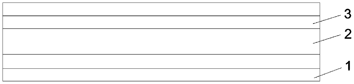
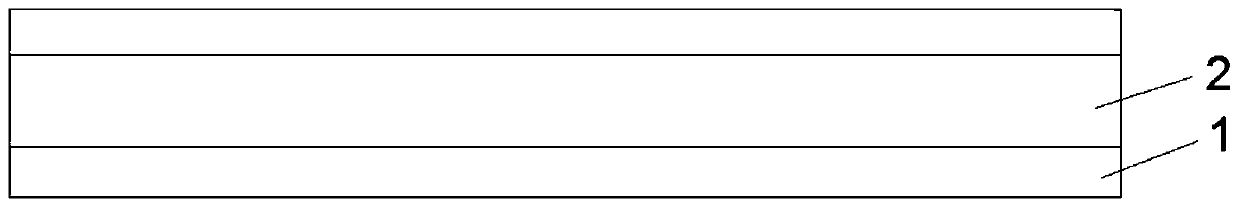
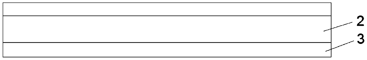
[0033] This embodiment provides a current collector, including a conductive layer 1, an insulating layer 2 and a reinforcing layer 3, the conductive layer 1 is two, and an insulating layer 2 is arranged between the two conductive layers 1, and the conductive layer 1 and the insulating layer 2 are also provided with the reinforcing layer 3 for enhancing the conductivity; specifically, the current collector is composed of conductive layer 1, reinforcing layer 3, insulating layer 2, reinforcing layer 3 and Conductive layer 1, the conductive layer 1, the reinforcing layer 3, and the insulating layer 2 are combined by sputtering;

[0034] The conductive layer 1 is aluminum foil with a thickness of 0.6 μm, and the aluminum foil is surface treated by one or more combinations of hot air blowing, pickling, corona, plasma, sandblasting, and grinding;

[0035] The insulating layer 2 is polyethylene terephthalate, and the thickness of the insulating layer 2 is 2 μm;

[0036] The reinforc...

Embodiment 2

[0038] This embodiment provides a current collector, including a conductive layer 1, an insulating layer 2 and a reinforcing layer 3, the conductive layer 1 is two, and an insulating layer 2 is arranged between the two conductive layers 1, and the conductive layer 1 and the insulating layer 2 are also provided with the reinforcing layer 3 for enhancing the conductivity; specifically, the current collector is composed of conductive layer 1, reinforcing layer 3, insulating layer 2, reinforcing layer 3 and Conductive layer 1, the conductive layer 1, the reinforcing layer 3, and the insulating layer 2 are composited by vacuum evaporation;

[0039] The conductive layer 1 is aluminum foil with a thickness of 0.8 μm, and the aluminum foil is surface treated by one or more combinations of hot air blowing, pickling, corona, plasma, sandblasting, and grinding;

[0040] The insulating layer 2 is epoxy resin, and the thickness of the insulating layer 2 is 4 μm;

[0041] The reinforcement...

Embodiment 3

[0043] This embodiment provides a current collector, including a conductive layer 1, an insulating layer 2 and a reinforcing layer 3, the conductive layer 1 is two, and an insulating layer 2 is arranged between the two conductive layers 1, and the conductive layer 1 and the insulating layer 2 are also provided with the reinforcing layer 3 for enhancing the conductivity; specifically, the current collector is composed of conductive layer 1, reinforcing layer 3, insulating layer 2, reinforcing layer 3 and Conductive layer 1, the conductive layer 1, the reinforcing layer 3, and the insulating layer 2 are composited by ion plating;

[0044] The conductive layer 1 is aluminum foil with a thickness of 1 μm, and the aluminum foil is surface treated by one or more combinations of hot air blowing, pickling, corona, plasma, sandblasting, and grinding;

[0045] The insulating layer 2 is polyimide, and the thickness of the insulating layer 2 is 5 μm;

[0046] The reinforcing layer 3 is a...


PUM

PropertyMeasurementUnit
thicknessaaaaaaaaaa
thicknessaaaaaaaaaa
thicknessaaaaaaaaaa

Abstract

The invention discloses a current collector and a lithium ion battery containing the current collector. The current collector comprises a conductive layer, an insulating layer and a reinforcing layer,wherein the number of the conducting layers is two, an insulating layer is arranged between the two conducting layers, and a reinforcing layer used for reinforcing conductivity is further arranged between the conducting layers and the insulating layer. The conductive layer, the enhancement layer and the insulating layer are compounded by adopting vacuum electroplating or electrolytic electroplating; the conductive layer is made of a metal material, wherein the thickness of the conductive layer is 0.1-1 [mu]m; the insulating layer is made of an organic polymer insulating material, wherein thethickness of the insulating layer is 2-8 microns; the enhancement layer is made of at least one of a carbon-based conductive material and a nano conductive ceramic material, wherein the thickness of the enhancement layer is 0.1-1 micron. The insulating layer is arranged between the two conductive layers, and the reinforcing layer is arranged between the conductive layers and the insulating layer,so the weight of the current collector is reduced, the conductivity of the current collector is ensured, the toughness of the current collector can be improved, and the consistency and safety of products are improved.

Description

technical field [0001] The invention belongs to the technical field of lithium ion batteries, and in particular relates to a current collector and a lithium ion battery containing the current collector. Background technique [0002] Due to the advantages of high energy density, high output power, long cycle life and low environmental pollution, lithium-ion batteries are not only widely used as power sources for portable electronic devices such as mobile phones, notebook computers, and digital cameras, but also as power sources for power tools, electric vehicles, etc. The device field has good prospects. A lithium-ion battery is composed of a positive electrode, a negative electrode and an electrolyte. The electrode sheet is an important part of the lithium-ion battery electrode. The current collector in the electrode sheet is the base metal for the positive or negative electrode of the battery to attach the active material. It is used for charging When the current is introd...

Claims


Application Information

Patent Timeline
Patent Type & Authority Applications(China)
IPC IPC(8): H01M4/66H01M10/0525
CPCH01M4/663H01M4/667H01M10/0525Y02E60/10
Inventor 韩俊女赵英杰
Owner 荆门市诺维英新材料科技有限公司
Why Eureka
Try Eureka