Load-measuring device for rolling bearing unit and rolling bearing unit for load measurement

a technology of load measurement and rolling bearing unit, which is applied in the direction of force measurement by elastic gauge deformation, instruments, force measurement apparatus, etc., can solve the problem of increasing the cost of the overall load measurement unit for the rolling bearing unit, and achieve the effect of manufacturing inexpensively

Active Publication Date: 2006-07-13
NSK LTD
View PDF3 Cites 9 Cited by
  • Summary
  • Abstract
  • Description
  • Claims
  • Application Information

AI Technical Summary

Benefits of technology

[0020] The load measuring unit for the rolling bearing unit of the present invention, as constricted above, can sense the axial load applied to this rolling bearing unit by sensing the revolution speed of the rolling elements. That is, the contact angle of the rolling elements (balls) is changed when the rolling bearing unit such as the double row angular contact ball bearing accepts the axial load. As well known in the technical field of the rolling bearing, the revolution speed of the rolling elements are changed when the contact angle is changed. More particularly, with respect to the row on the side that supports the axial load, the contact angle is increased as the axial load is increased. Then, the revolution speed is decelerated when the outer ring equivalent member is the rotary ring, and conversely the revolution speed is accelerated when the inner ring equivalent member is the rotary ring. Therefore, the axial load applied to this rolling bearing unit can be detected by measuring this change of the revolution speed. As the revolution speed sensor for sensing the revolution speed, the inexpensive speed sensor used widely to get the control signal of the ABS or the TCS in the prior art can be employed. For this reason, the overall load measuring unit for the rolling bearing unit can be manufactured inexpensively.

Problems solved by technology

As a result of above situation along with the fact that the load sensor 11 itself is expensive, it is unavoidable that a cost of the overall load measuring unit for the rolling bearing unit is considerably increased.

Method used


Image

  • Load-measuring device for rolling bearing unit and rolling bearing unit for load measurement
  • Load-measuring device for rolling bearing unit and rolling bearing unit for load measurement
  • Load-measuring device for rolling bearing unit and rolling bearing unit for load measurement

Examples


Embodiment Construction

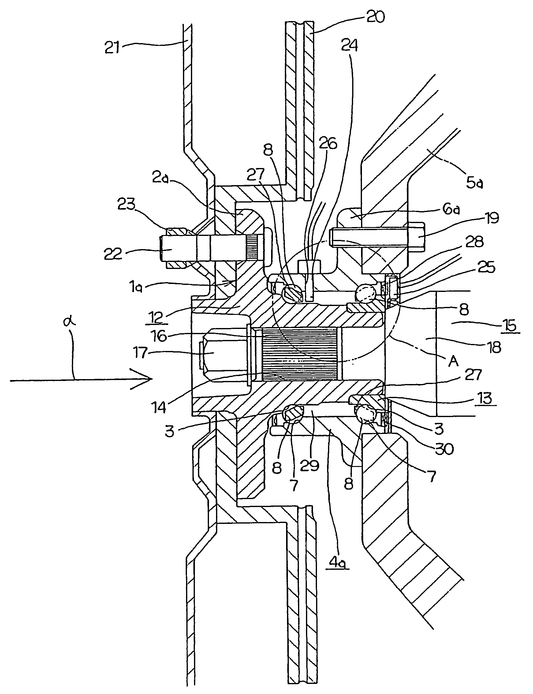
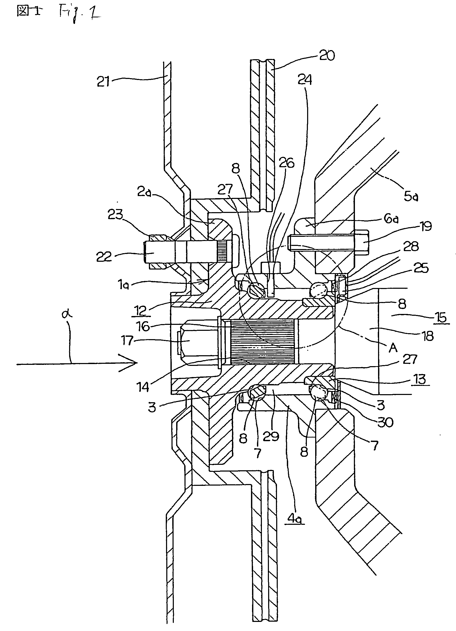
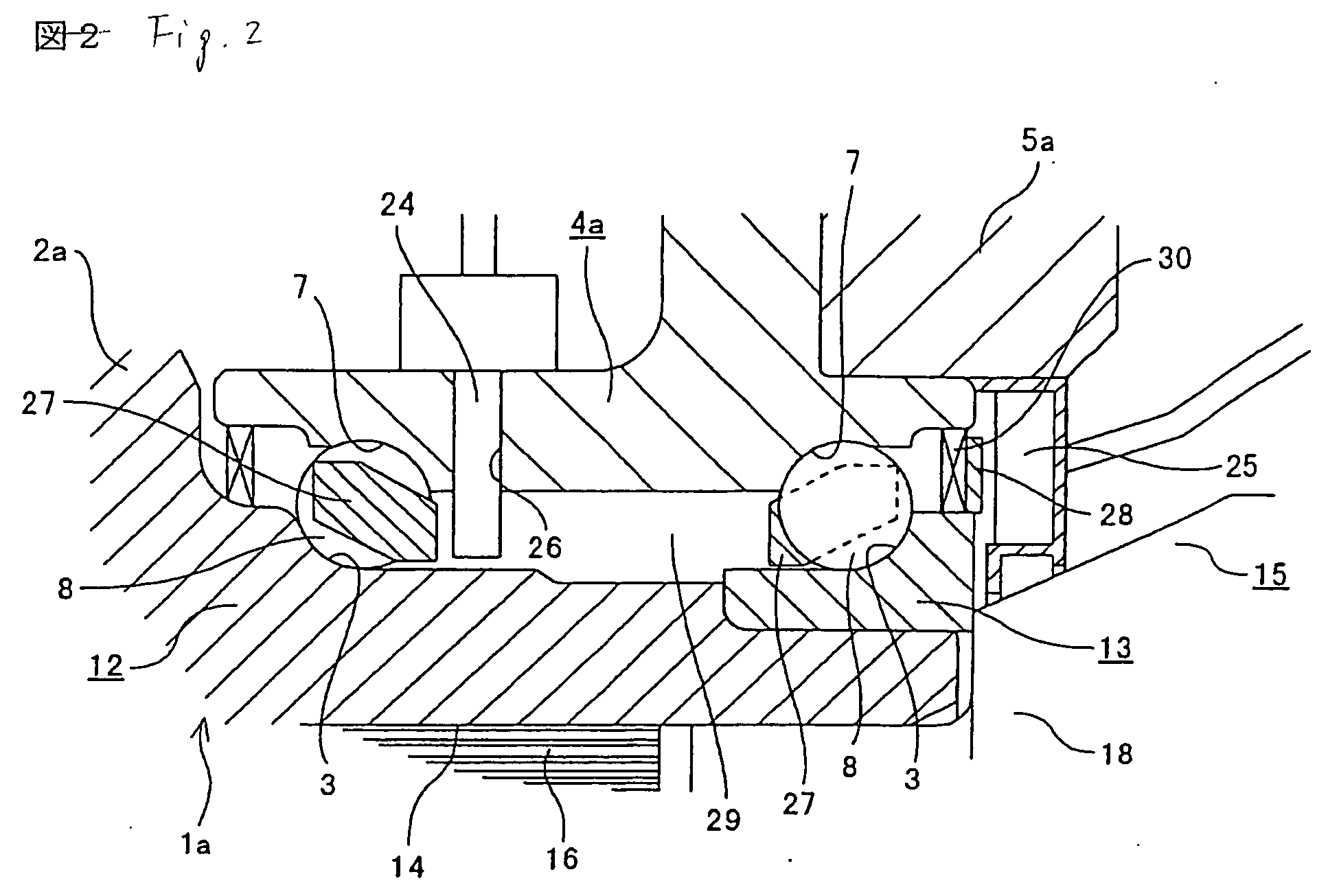
[0031]FIG. 1 and FIG. 2 show an example of embodiments of the present invention. This example shows the case where the present invention is applied to the rolling bearing unit used to support the driving wheel of the car (the rear wheel of the FR car, the RR car and the MD car, the front wheel of the FF car, and all wheels of the 4WD car). A hub 1a serving as the rotary ring and corresponding to the inner ring equivalent member is constructed by fitting / fixing an inner ring 13 onto an inner end portion of a hub main body 12. A rotary-side flange 2a for supporting the wheel is fixed to an outer peripheral surface of the outer end portion of the hub main body 12. Also, the inner ring raceways 3, 3 are formed on the outer peripheral surface of the middle portion of the hub main body 12 and the outer peripheral surface of the inner ring 13 respectively, so that double row angular contact inner ring raceways are provided on the outer peripheral surface of the hub 1a.

[0032] Meanwhile, a ...


PUM

PropertyMeasurementUnit
revolution speedaaaaaaaaaa
contact angleaaaaaaaaaa
rotation speedaaaaaaaaaa

Abstract

A revolution speed of balls 8, 8 constituting the outer side row is sensed by a revolution speed sensor 24. Also, a rotation speed of a hub 1a is sensed by a rotation speed sensor 25. A speed ratio as a ratio between a revolution speed and the rotation speed is calculated based on a sensed signal of both sensors 24, 25. When the axial load is changed and then the contact angles of the balls 8, 8 are changed, the revolution speed is changed and in turn the speed ratio is changed. Therefore, the axial load is calculated based on a change of the speed ratio.
Accordingly, the configurations that can be manufactured at a low cost and is able to sense the axial load applied between the hub 1a and the outer ring 4a can be realized.

Description

TECHNICAL FIELD [0001] A load measuring unit for a rolling bearing unit and a load measuring rolling bearing unit according to the present invention relates to improvements in the rolling bearing unit used to support a wheel of a mobile body such as a car, a railway vehicle, various carrier cars, or the like, for example, and is utilized to achieve promotion of the running stability of the mobile body by measuring an axial load applied to this rolling bearing unit. BACKGROUND ART [0002] The wheel of the car, for example, is supported rotatably by the suspension system via the double row angular contact rolling bearing unit. Also, in order to secure the running stability of the car, the vehicle running stabilizing system such as the anti-lock brake system (ABS), the traction control system (TCS), the vehicle stability control system (VSC), or the like is employed. In order to control various vehicle running stabilizing systems, various signals such as a rotation speed of the wheel, a...

Claims


Application Information

Patent Timeline
Patent Type & Authority Applications(United States)
IPC IPC(8): G06F15/00F16C19/18G01P3/487F16C19/52F16C33/58F16C41/00G01L5/00G01M13/04G01P15/00
CPCF16C19/186F16C19/522F16C2326/02G01L5/0023G01M13/04F16C41/007G01L5/00F16C33/58F16C19/18G01P3/487
Inventor YANAGISAWA, TOMOYUKIMATSUOKA, KATSUTOSHISAKATANI, IKUNORIKUMAGAI, SHIN
Owner NSK LTD
Why Eureka
Try Eureka