
Method of operating a single cylinder two-stroke engine

a two-stroke engine and single-cylinder technology, applied in the direction of machines/engines, electric control, ignition automatic control, etc., can solve the problems of affecting the operation of the two-stroke engine, affecting the operation of the machine, so as to reduce the exhaust gas value, suppress the ignition, and reduce the effect of fuel consumption

Active Publication Date: 2006-07-20
ANDREAS STIHL AG & CO KG
View PDF13 Cites 7 Cited by
  • Summary
  • Abstract
  • Description
  • Claims
  • Application Information

AI Technical Summary

Benefits of technology

[0006] It is an object of the invention to provide a method for operating a two-stroke engine with which a smooth running performance of the two-stroke engine can be achieved in a simple manner.

Problems solved by technology

In this way, there results a rough running of the two-stroke engine which becomes manifest especially with an intensely fluctuating running noise which can be disturbing for the operator.
Above all, at low rpms and shortly after the start of the two-stroke engine when the two-stroke engine is still cold, a late combustion or a delayed combustion can occur in the combustion chamber.
The late combustion in the combustion chamber leads to the situation that the pressure in the combustion chamber is increased when the transfer channels open into the combustion chamber.
A complete scavenging of the combustion chamber cannot take place because of the unfavorable pressure conditions.
This late combustion disturbs the mixture preparation for the next combustion cycle so that a permanent disturbance of the running performance of the two-stroke engine results.

Method used


Image

  • Method of operating a single cylinder two-stroke engine
  • Method of operating a single cylinder two-stroke engine
  • Method of operating a single cylinder two-stroke engine

Examples


Embodiment Construction

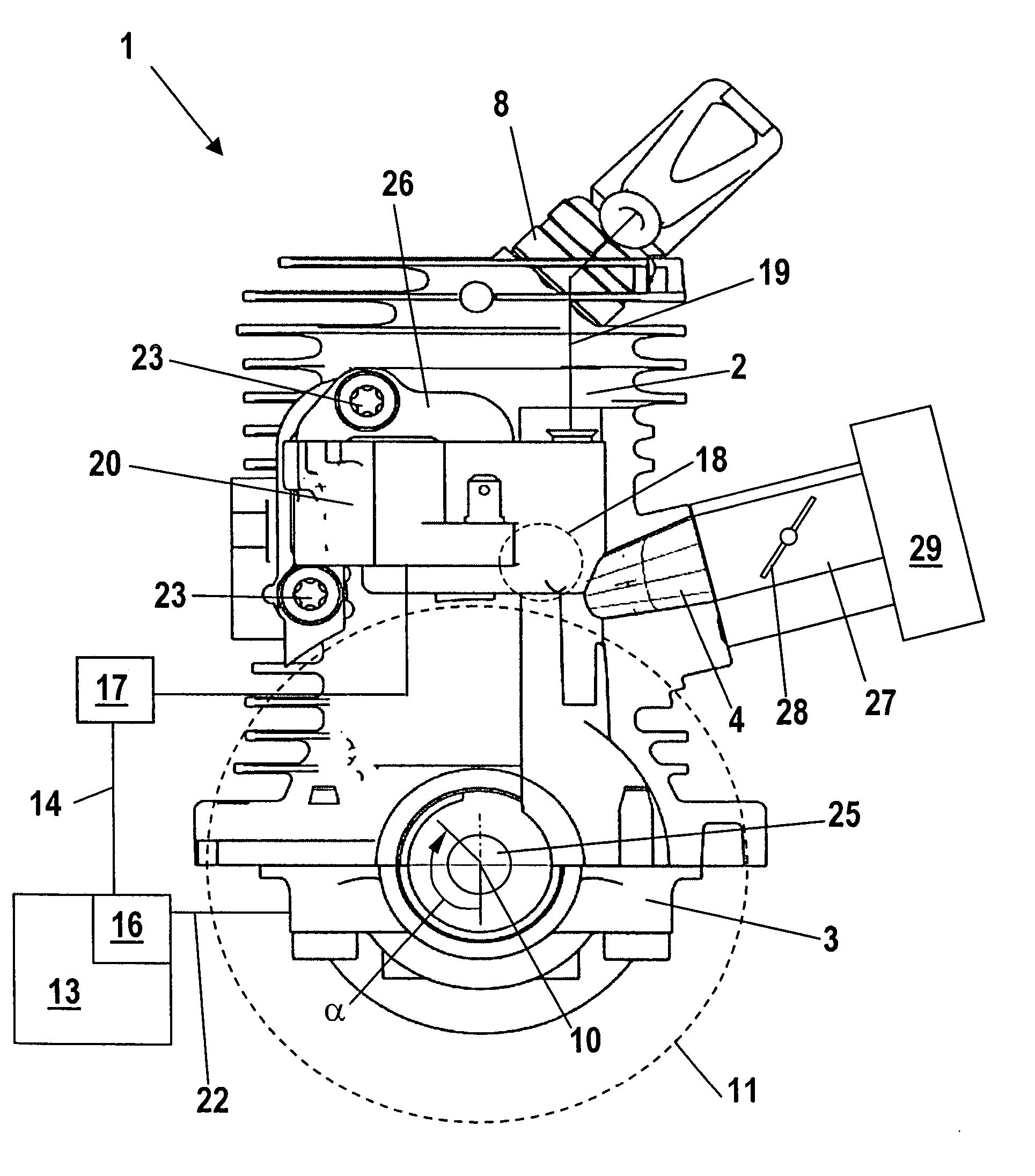
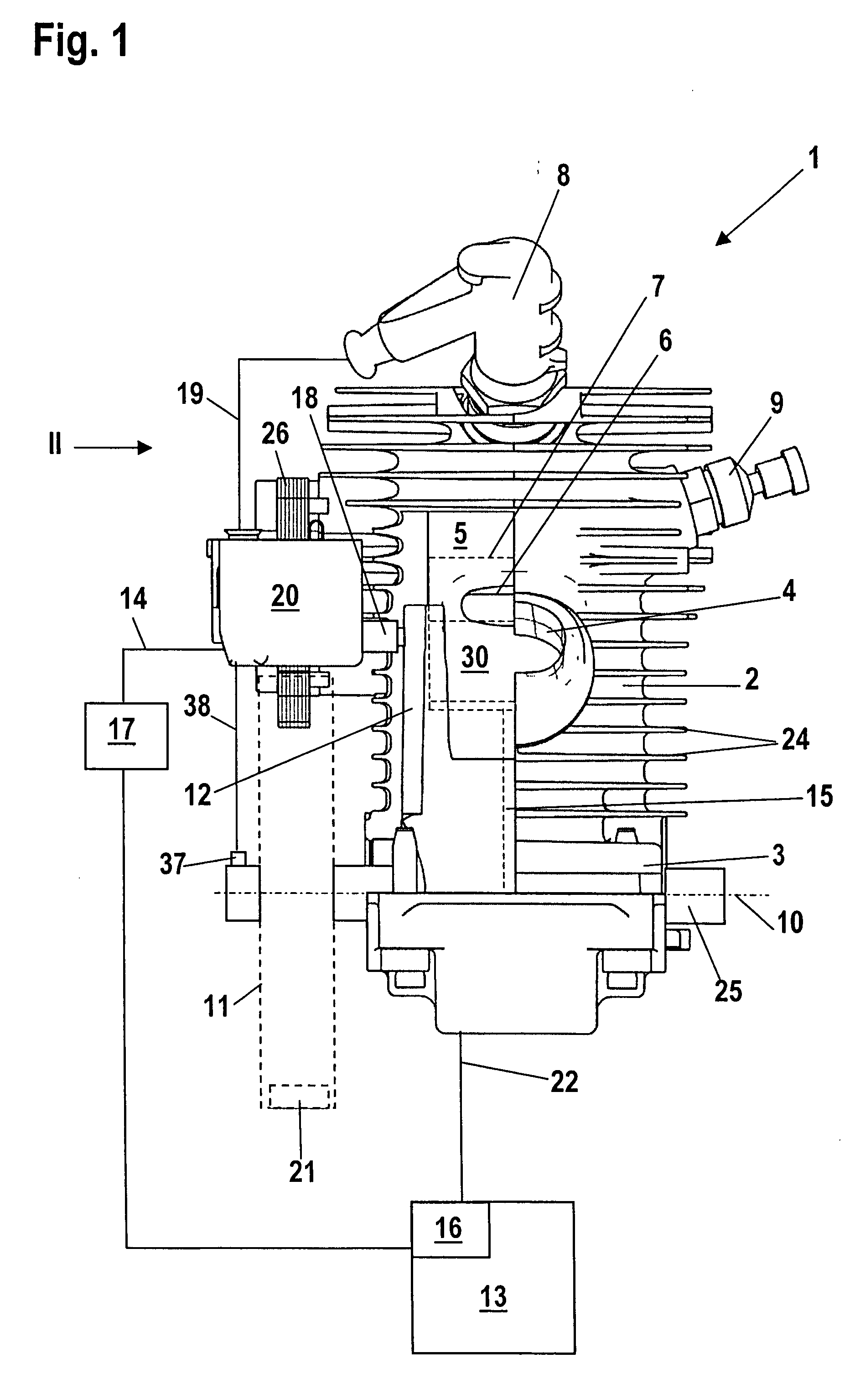
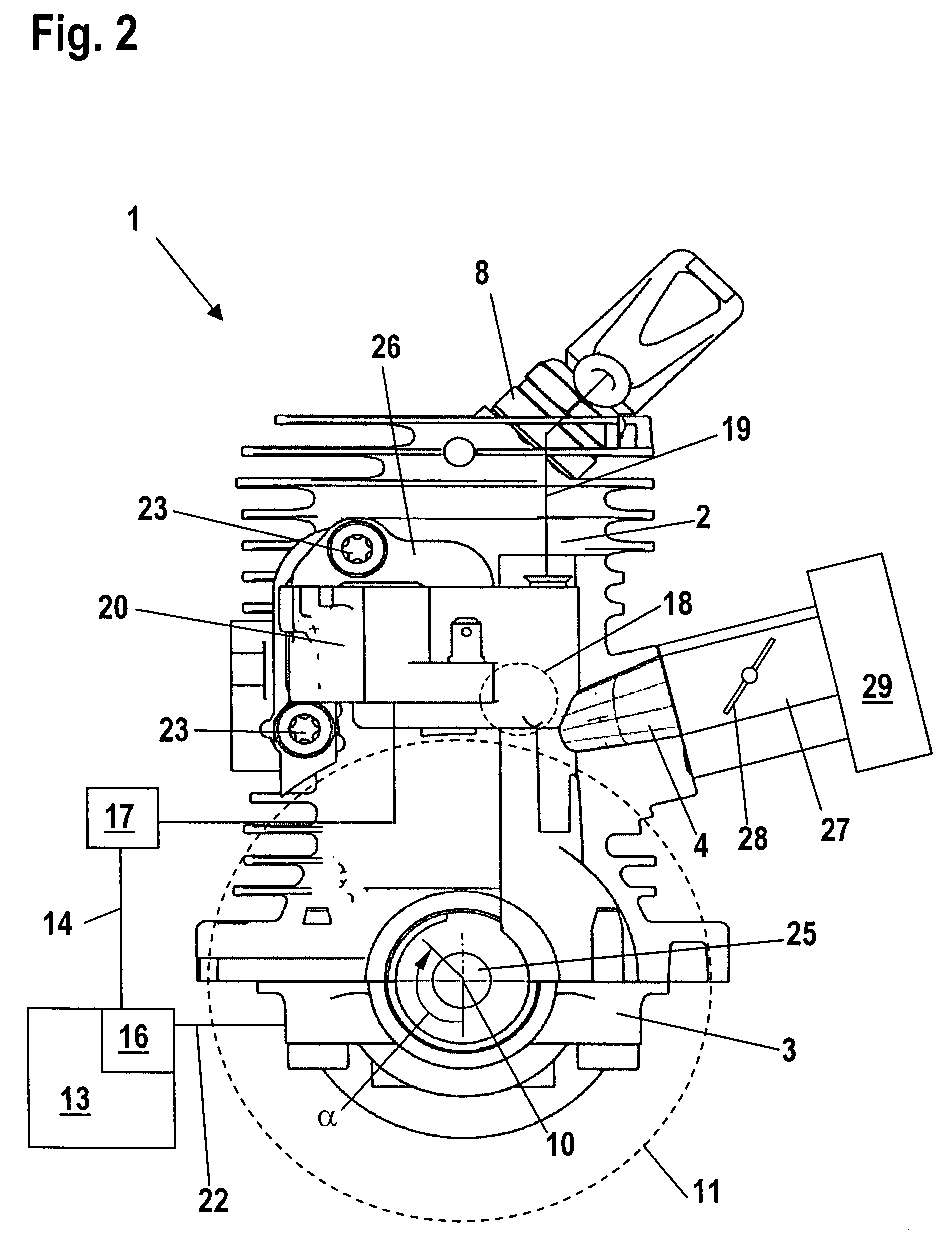
[0022] The two-stroke engine 1 shown in FIG. 1 has a cylinder 2 having cooling ribs 24 arranged on the outer surface thereof. A piston 7 is reciprocally journalled in the cylinder 2 and is shown in phantom outline. The piston 7 drives a crankshaft 25 via a connecting rod 15. The crankshaft 25 is rotatably journalled in a crankcase 3 about the crankshaft axis 10. An inlet 4 opens on the cylinder 2 via which substantially fuel-free combustion air is supplied to the two-stroke engine which is configured as a single cylinder engine.

[0023] The two-stroke engine includes at least one transfer channel 12 which connects the crankcase 3 to a combustion chamber 5 in the region of bottom dead center of the piston 7. The combustion chamber 5 is delimited by the cylinder 2 and the piston 7. Two or four transfer channels 12 are provided and are arranged symmetrically with respect to a partitioning center plane centered with respect to the inlet 4. The piston 7 has a piston pocket 30 indicated in...


PUM


Abstract

The invention is directed to a method for operating a two-stroke engine having a cylinder in which a combustion chamber is formed and which includes devices for metering fuel and supplying combustion air as well as an ignition device for igniting a mixture in the combustion chamber. In the method, fuel and combustion air are supplied to the engine and the mixture in the combustion chamber is ignited. The combustion chamber is delimited by a piston which drives a crankshaft rotatably journalled in a crankcase. A control is provided which controls the metering of fuel and the ignition of the mixture in the combustion chamber. In the method, the two-stroke engine is controlled in at least one operating state so that the number of combustions is less than the number of revolutions of the crankshaft in the same time interval.

Description

CROSS REFERENCE TO RELATED APPLICATION [0001] This application claims priority of German patent application no. 10 2005 002 273.1, filed Jan. 18, 2005, the entire content of which is incorporated herein by reference. FIELD OF THE INVENTION [0002] The invention relates to a method for operating a single cylinder two-stroke engine especially in a portable handheld work apparatus such as a portable chain saw, cutoff machine or the like. BACKGROUND OF THE INVENTION [0003] A two-stroke engine is disclosed in U.S. Pat. No. 5,901,673 wherein fuel is injected into the combustion chamber in the region of bottom dead center with each rotation of the crankshaft and the air / fuel mixture, which forms in the combustion chamber, is ignited in the region of top dead center of the piston. [0004] Two-stroke engines can pass into four-stroke operation especially at high rpms. This means that a combustion does not take place with each revolution of the crankshaft; instead, a combustion takes place only...

Claims


Application Information

Patent Timeline
Patent Type & Authority Applications(United States)
IPC IPC(8): F02B33/04F02M69/10F02B77/08
CPCF02B25/14F02D2400/04F02D41/061F02D41/08F02D41/1497F02D41/22F02P5/045F02D37/02F02D2200/1012F02D2200/1015F02D2400/06F02D41/3058
Inventor SCHIEBER, EBERHARDLEUFEN, HEINRICHABOU-ALY, MOHAMEDNICKEL, HANSROSSKAMP, HEIKOSCHLOSSARCZYK, JORGGEYER, KLAUS
Owner ANDREAS STIHL AG & CO KG
Learn More