Construction machine and projecting object of the same
a construction machine and projecting object technology, applied in soil shifting machines/dredgers, roofs, transportation and packaging, etc., can solve the problems of increasing the total weight of the vehicle, reducing the operability of the vehicle, and reducing work efficiency, so as to achieve low cost, facilitate production, and avoid interference with the components of the construction machine
- Summary
- Abstract
- Description
- Claims
- Application Information
AI Technical Summary
Benefits of technology
Problems solved by technology
Method used
Image
Examples
first embodiment
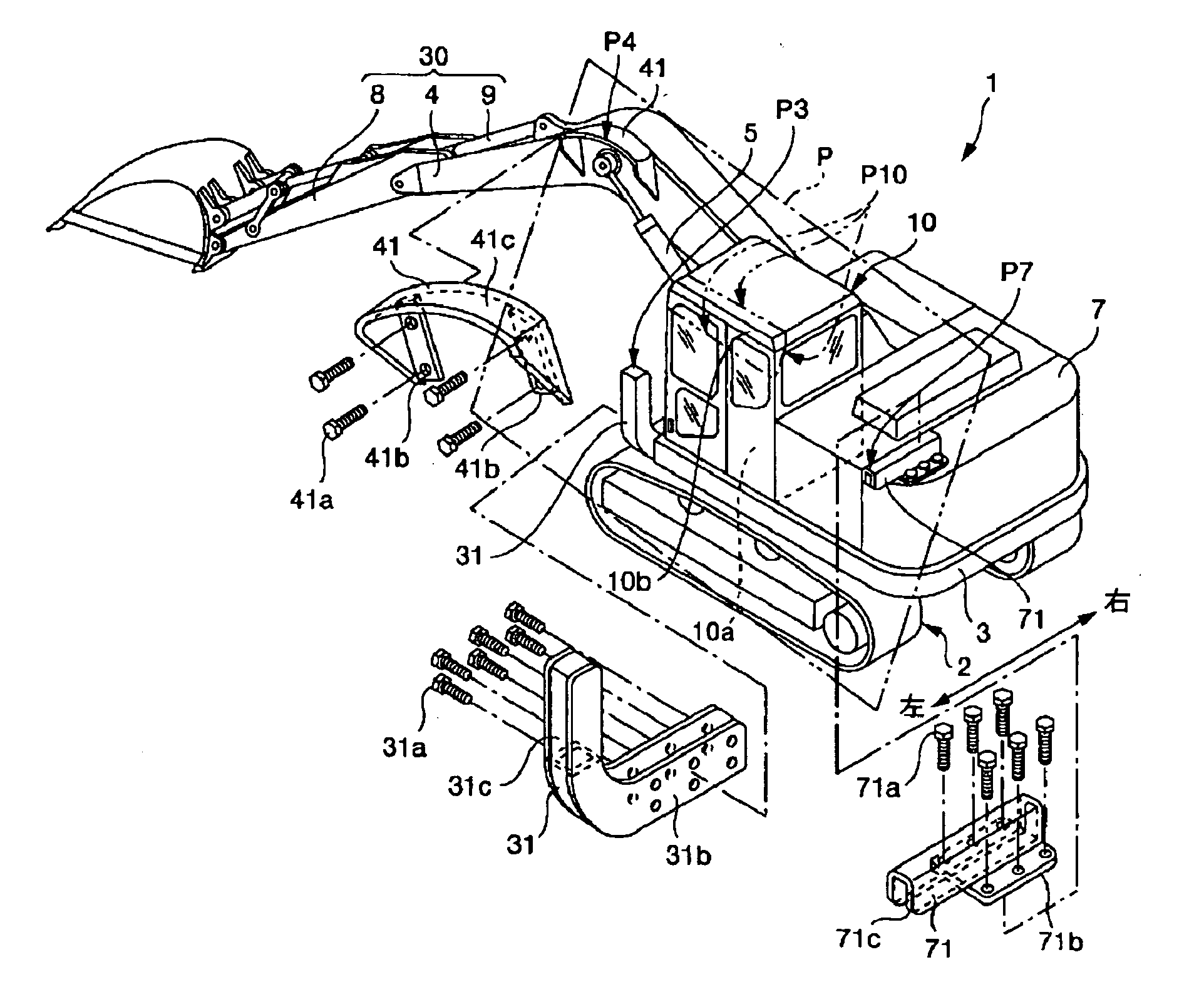
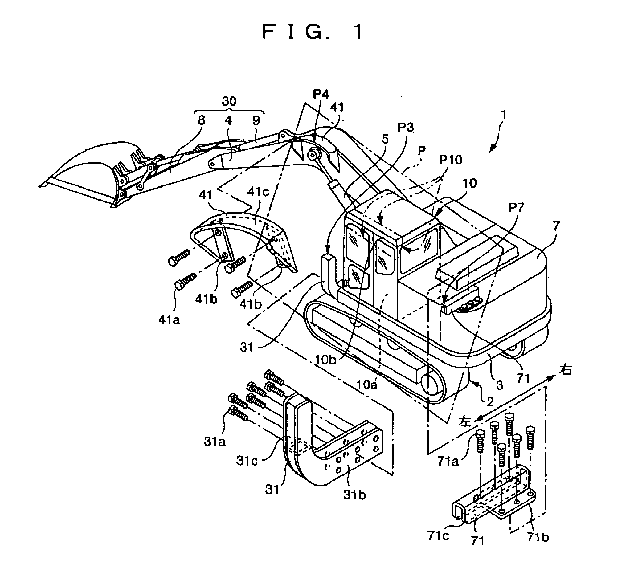
[0039] In the above-described structure, the respective leading ends P3, P4, P7 of the projecting members 31, 41, 71 define a virtual plane P. An operator's cab space 10a, which is located in an inner position of the vehicle body than the location of the intersecting line P10 of the virtual plane P and the operator's cab 10, provides a space large enough to allow the operator to work to repair and recover the construction machine 1 within the operator's cab 10 in case of overturning or tumbling. Although three projecting members 31, 41, 71 are provided in the first embodiment, the number of projecting members is not limited to this. In other words, at least any one of the three projecting members 31, 41, 71 is provided and the virtual plane P is defined by three points that are (i) the end of the revolving superstructure frame 3 which end is located on the side of the operator's cab 10 or the projecting member 31; (ii) the end of the boom 4 or the projecting member 41; and (iii) the...
second embodiment
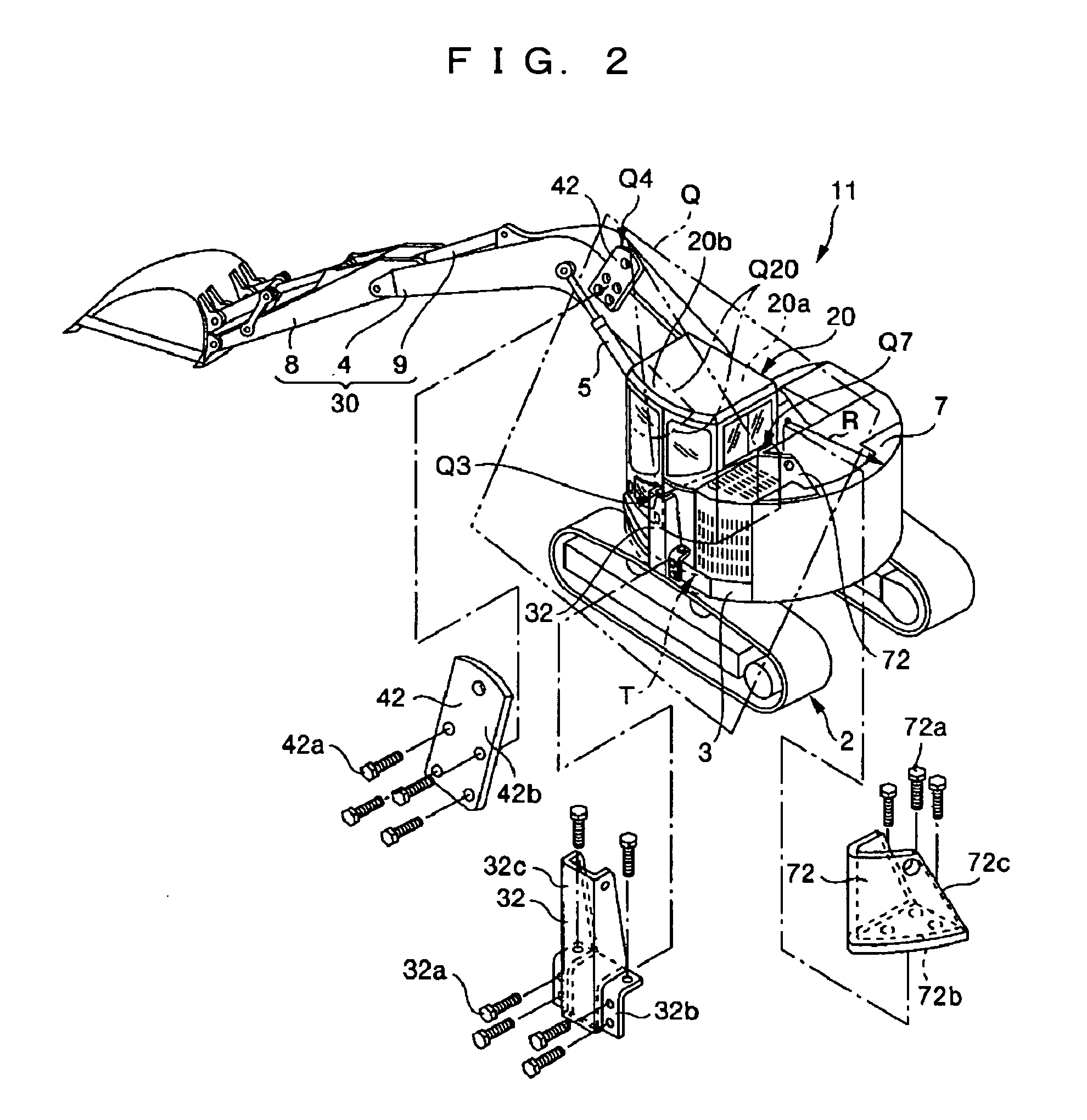
[0042] A projecting member 32 is disposed at an end of the revolving superstructure frame 3 which end is located at a transverse side of the operator's cab 20 (in the second embodiment, the left side of the operator's cab 20). The projecting member 32 is located within the turning radius R of the revolving superstructure frame 3. The projecting member 32 is a welded structure formed such that a supporting member 32c of U-shaped cross-section is welded to a base end member 32b serving as an attaching part, so as to project upward, and such that the base end member 32b is detachably bolted to the revolving superstructure frame 3 with a specified number of bolts 32a. A projecting member 42, which is composed of an upwardly projecting plate 42b, is detachably bolted to the boom 4 with a specified number of bolts 42a. Preferably, the projecting member 42 is disposed in the vicinity of a substantially length-wise mid position that becomes the highest position when the boomerang-like boom ...
fourth embodiment
[0047] The fourth embodiment is associated with another embodiment of the projecting member disposed at the end of the counterweight 7. To eliminate an influence upon the transportability of the construction machine by avoiding an increase in vehicle width, a projecting member 73, which projects rearward from the counterweight 7, is disposed on the upper face of the counterweight 7 on the same side as the operator's cab. The projecting member 73 is a welded structure composed of a plate-like base end member 73b serving as an attaching part and a supporting member 73c of U-shaped cross-section which is welded to the upper face of the base end member 73b, with the opening end of the member 73c down, such that the supporting member 73c takes the form of a rectangular column extending in a horizontal direction. The projecting member 73 is arranged such that the leading end of the supporting member 73c projects rearward from the counterweight 7 and the base end member 73b is detachably b...
PUM
 Abstract
Description
Claims
Application Information
 - R&D
- Intellectual Property
- Life Sciences
- Materials
- Tech Scout
- Unparalleled Data Quality
- Higher Quality Content
- 60% Fewer Hallucinations
Browse by: Latest US Patents, China's latest patents, Technical Efficacy Thesaurus, Application Domain, Technology Topic, Popular Technical Reports.
© 2025 PatSnap. All rights reserved.Legal|Privacy policy|Modern Slavery Act Transparency Statement|Sitemap|About US| Contact US: help@patsnap.com


