Image forming device and image forming method

Inactive Publication Date: 2006-07-20
RICOH KK
View PDF13 Cites 59 Cited by
  • Summary
  • Abstract
  • Description
  • Claims
  • Application Information

AI Technical Summary

Benefits of technology

[0042] According to the present invention, it is possible to satisfactorily correct a position shift even when installation environment changes or unexpected shocks occur

Problems solved by technology

However, scanning speed correction with the fθ lens has its limit; it cannot attains accurate regular intervals of the positions of the beam spots on the scanning surface.
In other words, there exists unevenness of the intervals of beam spot positions.
When the unevenness of the intervals of beam spot positions is present, image distortion occurs, resulting in degradation of image quality.
Further, in a color image forming device, a number of fθ lenses are used, and because of uncertainties

Method used


Image

  • Image forming device and image forming method
  • Image forming device and image forming method
  • Image forming device and image forming method

Examples


Embodiment Construction

[0071] Below, preferred embodiments of the present invention are explained with reference to the accompanying drawings.

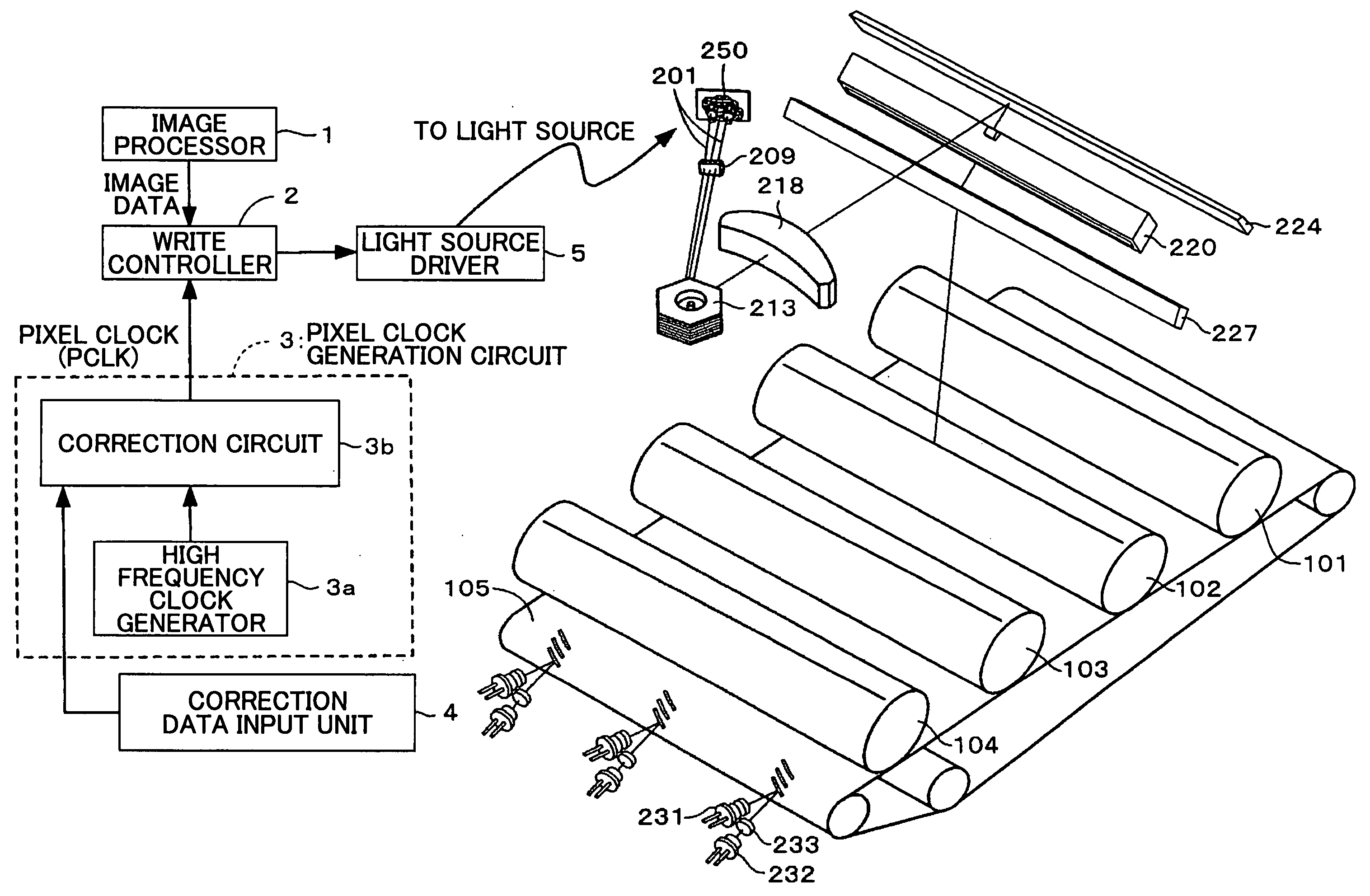
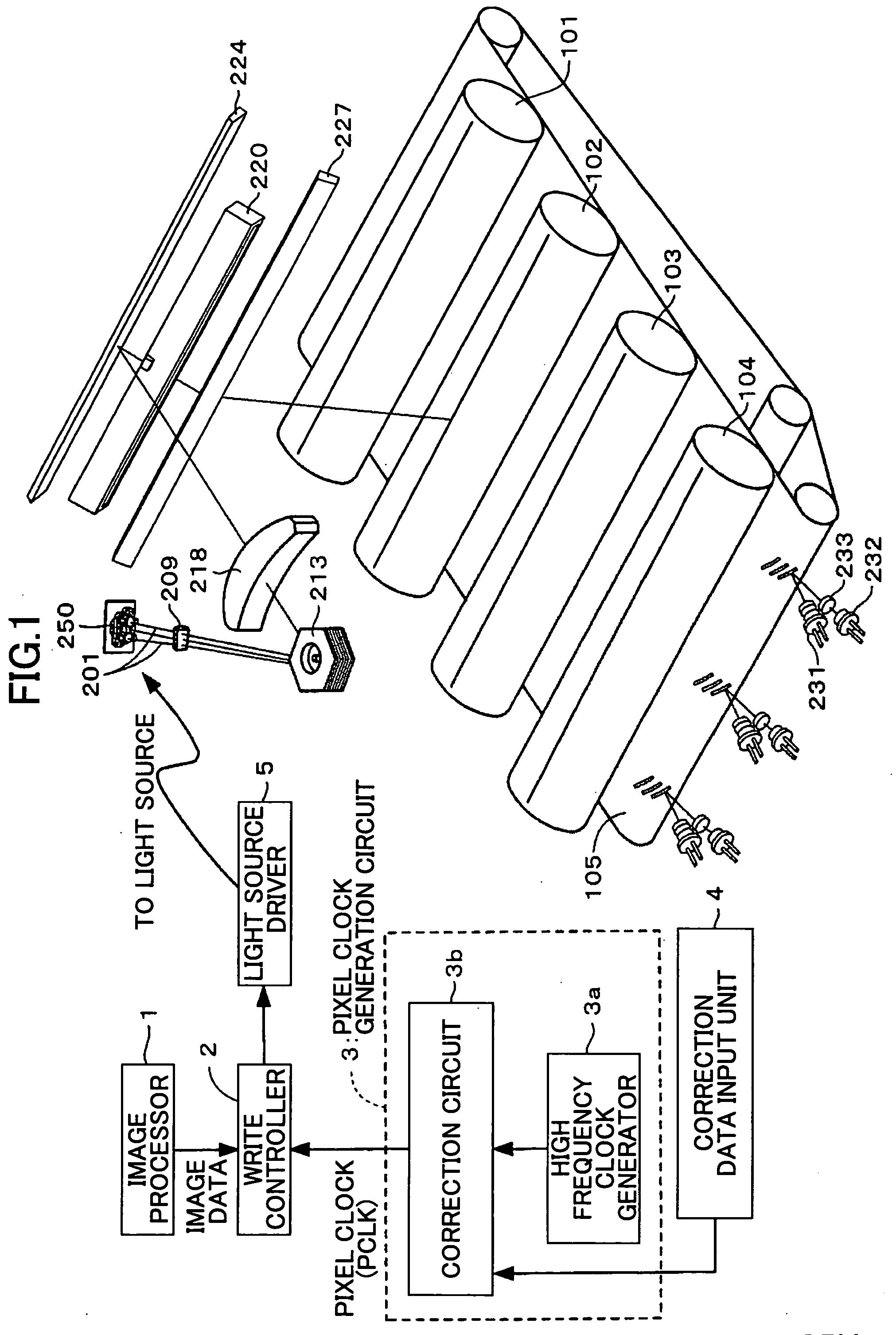
[0072]FIG. 1 is schematic view illustrating a structure of an image forming device according to an embodiment of the present invention.

[0073] The image forming device shown in FIG. 1 includes an image processor 1, a write controller 2, a pixel clock generation circuit 3, a high frequency clock generator 3a, a correction circuit 3b for correcting unevenness of beam spot position intervals, a correction data input unit 4 for inputting correction data of beam spot positions, a light source driver 5, a beam spot position correction unit 10, photoconductors 101 to 104, a transfer belt 105, a cylindrical lens 209 for correcting an optical face angle error, a polygonal mirror 213, a fθ lens 218 as a first condensing lens, a toroidal lens 220 as a second condensing lens, mirrors 224, 227, a projection element 231, a light receiving element 232, a light receiving lens 233,...


PUM


Abstract

An image forming device is disclosed that is able to correct an image distortion even when the installation environment changes or unexpected shocks occur and even when an optical scanning device is exchanged. The image forming device comprises a light source, an optical scanning unit, a development unit, a transfer unit, a test image output unit to output a test image able to determine unevenness of intervals of positions of beam spots formed on an image supporting member, a beam spot position correction unit to correct the unevenness of the beam spot position intervals, and a correction data input unit to select correction data of the unevenness of the beam spot position intervals.

Description

BACKGROUND OF THE INVENTION [0001] 1. Field of the Invention [0002] The present invention relates to a technique of correcting image distortion in a digital copier, a laser printer, a laser facsimile, or others, and in particular, relates to a technique of correcting position or color shift in an image forming device. [0003] 2. Description of the Related Art [0004] Generally, in an optical scanning device, which is well-known as being relevant to a laser printer, a laser beam from a light source is deflected by an optical deflector, condensed by a scanning-imaging optical system, such as a fθ lens, toward a surface to be scanned (below, referred to as a “scanning surface”), forming a light spot on the scanning surface. The light spot is moved on the scanning surface to perform optical scanning (main scanning). The scanning surface is the photosensitive surface of a photoconductor, which is photoconductive and serves as a photosensitive medium. [0005] Generally, the optical deflector...

Claims


Application Information

Patent Timeline
IPC IPC(8): G02B26/08
CPCG02B26/127G02B27/0031H04N1/047H04N1/1135H04N1/12H04N2201/0471H04N2201/0476H04N2201/04717
Inventor IMAI, SHIGEAKINAKAJIMA, TOMOHIRO
Owner RICOH KK
Why Eureka
Try Eureka