
Wireless communication apparatus and wireless communication method

a wireless communication and wireless communication technology, applied in the field of wireless communication apparatus and wireless communication method, can solve the problems of channel information exchange between the transmitter and the receiver, error remains, communication and symbol interference, etc., and achieve the effect of expanding the transmission capacity

Active Publication Date: 2006-07-20
REDWOOD TECHNOLOGIES LLC
View PDF7 Cites 40 Cited by
  • Summary
  • Abstract
  • Description
  • Claims
  • Application Information

AI Technical Summary

Benefits of technology

[0035] It is desirable to provide a wireless communication apparatus and a wireless communication method excellent at being able to expand the transmission capacity by carrying out MIMO communication which uses spatial multiplexing and forms a plurality of logical channels, pairing a transmitter having a plurality of antennas with a receiver having a plurality of antennas.
[0036] Further, it is desirable to provide a wireless communication apparatus and a wireless communication method excellent at being able to solve the problem of a frequency error of a reception signal when a receiver performs MIMO synthesis on signals received from a plurality of antennas to spatially separate the signals into a plurality of orthogonal MIMO channels.
[0037] Furthermore, it is desirable to provide a wireless communication apparatus and a wireless communication method excellent at being able to solve the problem of a frequency offset of a frequency error and a timing drift when a receiver performs MIMO synthesis on signals received from a plurality of antennas to spatially separate the signals into a plurality of orthogonal MIMO channels.

Problems solved by technology

However, it is an issue how channel information is exchanged between the transmitter and the receiver in accordance with an antenna configuration.
A multipath produces delay distortion (or frequency selective fading), thereby causing an error in communication and interference between symbols.
However, there is a problem of a residual frequency offset that an error remains in the case where an error arises in calculating a frequency offset due to noise etc.
However, since the receiver merely corrects frequency offsets at the head (preamble) of a packet, as shown in FIG. 8 phase shifts are accumulated as OFDM symbols continue, thereby degrading the communication quality.
Further, in the multicarrier transmission system, there is a problem that a timing drift occurs during long continuous data symbols.
On the other hand, the MIMO receiver which synthesizes signals received from a plurality of antennas can perform synchronization acquisition and frequency correction using the preambles of the reception signals before MIMO synthesis; however, there is a problem that errors after frequency correction, i.e., residual frequency offsets are subjected to MIMO synthesis.
As described above, in the case of a long packet length, the MIMO-synthesized residual errors are accumulated as data symbols continue, thereby causing the phase rotation and phase twist which lead to errors.
Especially in high modulation modes such as 64QAM and 256QAM, the communication is more susceptible to residual errors, thereby obstructing the achievement of high-throughput data transmission.
However, the wireless signal receiving apparatus extracts only pilot subcarriers having fixed phases before MIMO synthesis and estimates frequency errors by calculating the autocorrelation among OFDM symbols.
In other words, residual components after the frequency correction are not treated; therefore, it may be impossible to eliminate the influence of phase rotations and phase twists by the MIMO-synthesized residual errors.

Method used


Image

  • Wireless communication apparatus and wireless communication method
  • Wireless communication apparatus and wireless communication method
  • Wireless communication apparatus and wireless communication method

Examples


Embodiment Construction

[0069] Hereinafter, embodiments of the present invention will be described in detail with reference to the accompanying drawings.

[0070] The invention can be applied to a MIMO communication system. In the MIMO communication system, a transmitter and / or a receiver performs antenna synthesis in such a manner that the transmitter having a plurality of antennas and the receiver having a plurality of antennas make a pair and form a plurality of logical channels independent of each other, namely MIMO channels. According to the MIMO communication system, a plurality of RF transmission / reception units are put together in one wireless apparatus, thereby realizing large-capacity data transmission.

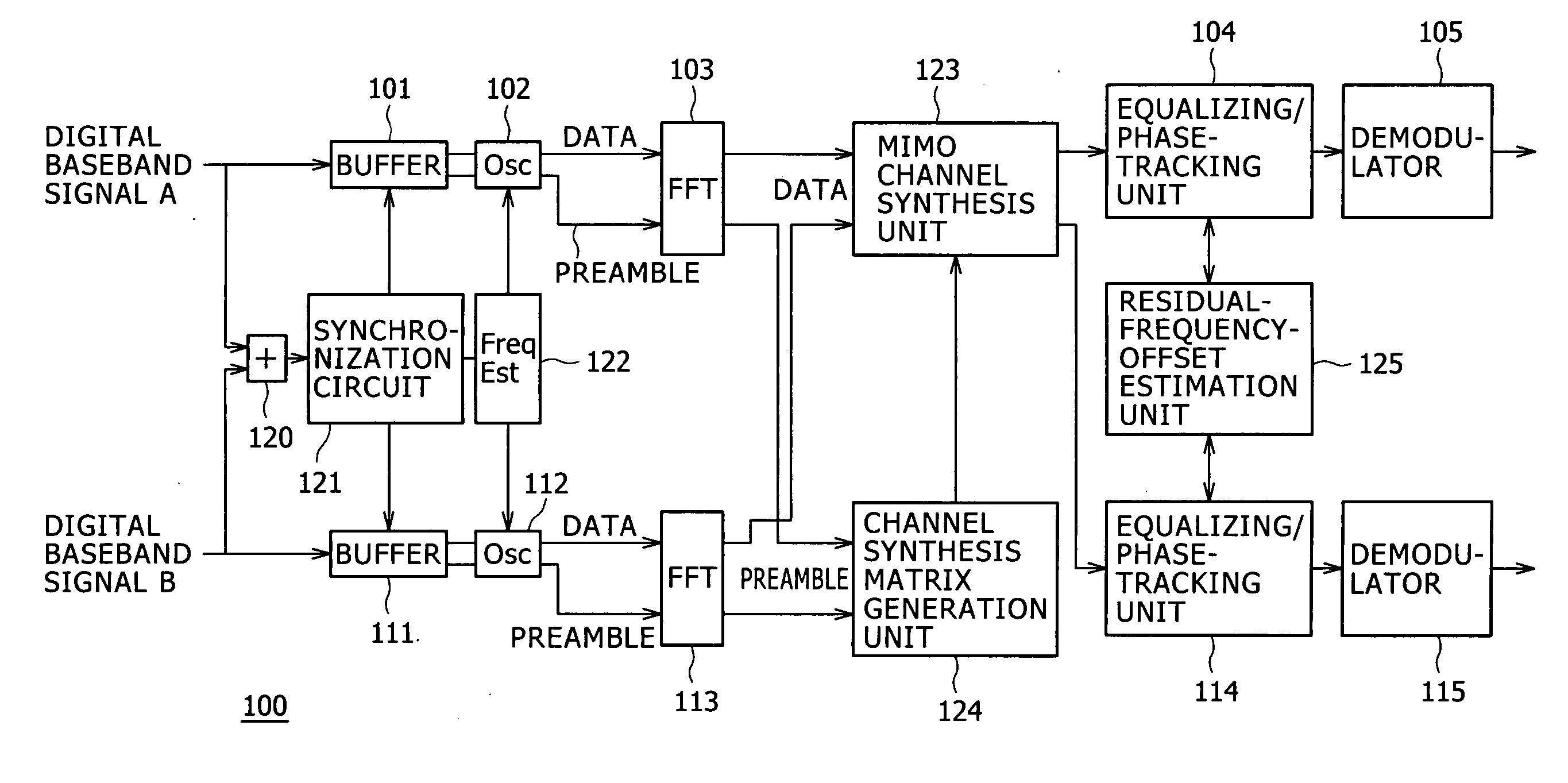
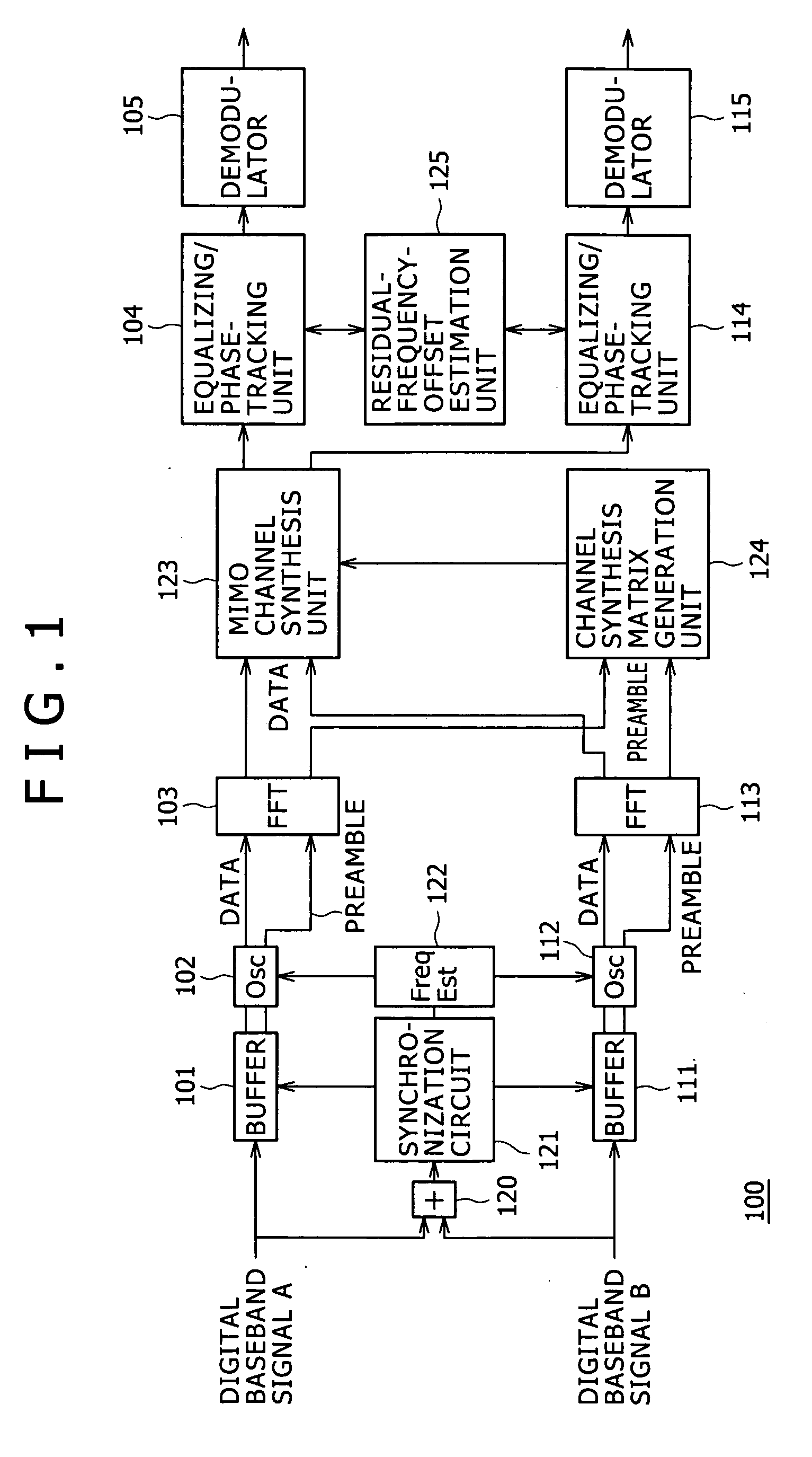
[0071]FIG. 1 shows a schematic block diagram of a wireless communication apparatus according to an embodiment of the present invention. A wireless communication apparatus 100 shown in FIG. 1 can operate as a MIMO receiver. In the example of FIG. 1, two antenna routes are employed for simplicity of e...


PUM


Abstract

Disclosed is a wireless communication apparatus which synthesize signals received from a plurality of antennas to separate the signals into synthesis signals of a plurality of logical channels. The apparatus has a first phase corrector correcting a phase of a reception signal by estimating an amount of phase correction by a frequency offset of each reception signal from the plurality of antennas; a synthesizer synthesizing reception signals after phase correction by the first phase corrector to separate the reception signals into synthesis signals of a plurality of logical channels; and a second phase corrector correcting a phase of a synthesis signal by estimating an amount of phase correction by a residual frequency offset after phase correction by the first phase corrector based on the synthesis signal synthesized by the synthesizer.

Description

CROSS REFERENCES TO RELATED APPLICATIONS [0001] The present invention contains subject matter related to Japanese Patent Application No. 2004-378944 filed in the Japanese Patent Office on Dec. 28, 2004, the entire contents of which being incorporated herein by reference. BACKGROUND OF THE INVENTION [0002] 1. Field of the Invention [0003] The present invention relates to a wireless communication apparatus and a wireless communication method for realizing broadband wireless transmission between a plurality of wireless stations, such as a wireless LAN (Local Area Network) or PAN (Personal Area Network). In particular, the invention relates to a wireless communication apparatus and a wireless communication method for expanding the transmission capacity by carrying out MIMO (Multi Input Multi Output) communication which uses spatial multiplexing and forms a plurality of logical channels, pairing a transmitter having a plurality of antennas with a receiver having a plurality of antennas. ...

Claims


Application Information

Patent Timeline
IPC IPC(8): H04K1/10
CPCH04L1/0631H04L27/2679H04L27/2659H04L27/266H04L27/2675
Inventor IZUMI, SEIICHI
Owner REDWOOD TECHNOLOGIES LLC
Learn More