
Three-dimensional cad system

a three-dimensional cad and system technology, applied in the field of three-dimensional cad (computer-aided design), can solve the problems of difficult simulation that takes into account the operation in an environment that approaches the state in which a device is actually assembled, and cannot reflect the operational tolerances of simulation, so as to reduce the number of design trials and units, improve the development and design environment, and reduce the effect of development and design costs

Inactive Publication Date: 2006-07-20
CANON KK
View PDF9 Cites 57 Cited by
  • Summary
  • Abstract
  • Description
  • Claims
  • Application Information

AI Technical Summary

Benefits of technology

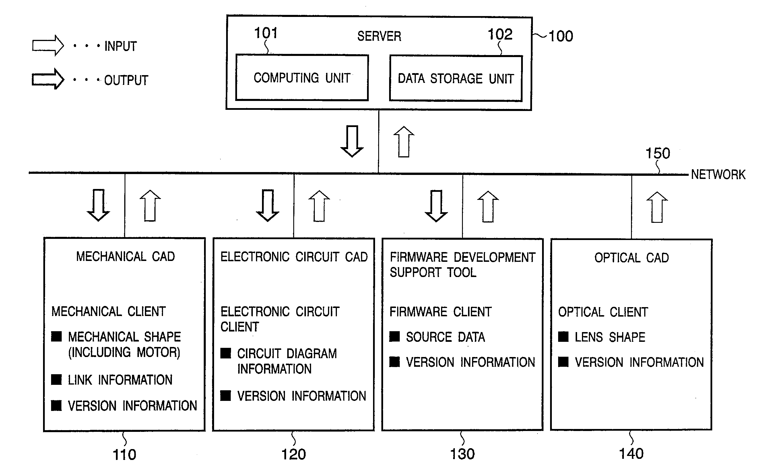
[0011] According to another aspect of the present invention, there is provided a server system in a three-dimensional CAD system comprising: a server; and, a plurality of clients, the server and the plurality of clients connected by a network, the server comprising a data storage unit that stores data and a computing unit that reads and writes data to and from the data storage unit in response to requests from the clients and generates a three-dimensional model and an operating simulation of such three-dimensional model, the server making it possible to display on a given client side an operating simulation linked to design data according to other clients by using the computing unit to generate operating simulation data for a three-dimensional model generated by causing design data according to the other clients to be reflected in a three-dimensional model generated based on design data from the given client, and transmits such generated operating simulation data to the given client over the network.
[0013] According to the present invention, in a 3D CAD system composed of a server and a plurality of clients, data designed by the clients can be shared, thus allowing simulations that combine elements that have been designed separately, for example, mechanical, electronic circuit, software, optical components and the like, and therefore making possible simulations as completed products even without complete assembly of the test product, thereby greatly improving the development and design environment, permitting the number of design trials and units to be reduced, and greatly reducing development and design costs. In addition, the present invention provides the ability to simulate design targets at the design stage, permitting visual confirmation of the movements of such design targets, and thus facilitates parallel design and joint testing with other designers as well as reduction in specification errors.

Problems solved by technology

As a result, such simulation cannot reflect the operational tolerances and erroneous operations of the mechanical components that occur due to shifts in control timing and the like attendant upon electronic circuit noise, signal distortion and so forth arising when operating in a state in which the mechanical units have actually been assembled.
Consequently, although it is possible to design and to simulate the operation of each and every mechanical unit, it is difficult to perform a simulation that takes into consideration operation in an environment that approaches the state in which a device is actually assembled.
Moreover, ordinarily, these individual development systems are not compatible.
Therefore, mechanical design proceeds leaving open the possibility that the mechanism will not perform as desired when the control program that is ultimately developed is used.
However, because CAD systems are incompatible, importation is not easy but takes time and effort.
In addition, complete importation is sometimes unattainable due to limitations on simulation capability.
Similarly, despite the necessity of ultimately operating in tandem together with other design systems, because linkage between individual design systems at the design stage is not possible it takes time and effort to make adjustments until the design is finalized.
Accordingly, when carrying out design in an environment in which a plurality of different development systems coexists, it is extremely difficult to share data between development environments during design.

Method used


Image

  • Three-dimensional cad system
  • Three-dimensional cad system
  • Three-dimensional cad system

Examples


Embodiment Construction

[0025] Preferred embodiments of the present invention will now be described in detail in accordance with the accompanying drawings.

[0026]FIG. 1 is a diagram showing the basic configuration of a 3D CAD system according to an embodiment of the present invention. In the diagram, reference numeral 100 designates a server that comprises the vital center of the system, 110 designates a mechanical CAD as a client that carries out design of mechanical units that comprise a device, and 120 designates an electronic circuit CAD as a client for carrying out design of electronic circuit parts of the device. In addition, reference numeral 130 designates a firmware development support tool for development of, and development support for, a program (firmware) that controls the mechanical units and the electronic circuit parts of the device, and 140 designates an optical CAD that designs a lens unit and other optical components.

[0027] The server 100, and the clients composed of the mechanical CAD ...


PUM


Abstract

A CAD system having a plurality of clients connected by a network enables simulations to be run that reflect design information from other client CADs. A server 100 causes a computing unit 101 to reflect in a three-dimensional model generated based on design according to any given client 110-140 design data according to any other client 110-140. Then, using that three-dimensional model, the server carries out an operating simulation and transmits the simulation results to the requesting client. The client that receives the simulation results from the server 100 then displays those simulation results on a design screen.

Description

FIELD OF THE INVENTION [0001] The present invention relates to a three-dimensional CAD (Computer-Aided Design) composed of a server and a plurality of clients connected to that server by a network. In addition, the present invention relates to a server system in a 3D CAD system and a client CAD system in a 3D CAD system. BACKGROUND OF THE INVENTION [0002] Conventionally, in the field of mechanical design a three-dimensional CAD system is used, providing the ability to design mechanisms and mechanical components of mechanisms while displaying them in three dimensions. [0003] In order to support the development of a control program to control a dynamic component such as an actuator or a motor, for example, or a sensor or the like, a system of this type has the capability not to actually assemble a mechanism but to simulate the operation of each constituent component. A 3D CAD system capable of this type of simulation is disclosed, for example, in Japanese Patent Application Laid-Open ...

Claims


Application Information

Patent Timeline
IPC IPC(8): G06F17/50
CPCG06F17/50Y02T10/82G06T19/20G06T2219/2004G06T2219/2008G06F30/00
Inventor HAMATANI, MASAHIDEYOKOO, AKITOSATO, HIDEKAGEEGUCHI, NOBUAKI
Owner CANON KK
Learn More