Piezoelectric vibration gyro element, structure for supporting the piezoelectric vibration gyro element and gyro sensor

a technology of piezoelectric vibration and gyro sensor, which is applied in the direction of acceleration measurement using interia force, turn-sensitive devices, instruments, etc., can solve the problems of /i>and , amplitude of vibration of vibration detection arms, and decrease of sensitivity for detecting angular velocity, so as to improve the support strength

Inactive Publication Date: 2006-07-27
SEIKO EPSON CORP
View PDF4 Cites 21 Cited by
  • Summary
  • Abstract
  • Description
  • Claims
  • Application Information

AI Technical Summary

Benefits of technology

[0010] An advantage of an aspect of the present invention is that it provides a piezoelectric vibration gyro element which does not readily form fin-like irregular portions on the beams extending from the base portion, maintains sensitivity for detecting the angular velocity, and can be decreased in size, a structure for supporting the piezoelectric vibration gyro element and a gyro sensor.
[0020] Therefore, there can be provided a piezoelectric vibration gyro element maintaining sensitivity for detecting the angular velocity and which also can be decreased in size.
[0022] According to this constitution, the piezoelectric vibration gyro element is balanced, and a stable attitude is maintained.
[0026] According to this constitution, the fixing member having elasticity relaxes the vibration or the shock from the outer side making it possible to stably maintain the driving vibration and the detection vibration of the piezoelectric vibration gyro element. The fixing member works as a buffer member for the slight vibration that does leak to the support portions, so that the driving vibration and the detection vibration are little affected.
[0033] According to this constitution, there is provided a small gyro sensor maintaining a sensitivity for detecting the angular velocity of a piezoelectric vibration gyro element, improving the support strength and mounting the piezoelectric vibration gyro element of a small size.

Problems solved by technology

Therefore, there arouses a problem in that the amplitude of vibration of the vibration detection arms 101a and 101b decreases, and the sensitivity for detecting the angular velocity decreases.

Method used


Image

  • Piezoelectric vibration gyro element, structure for supporting the piezoelectric vibration gyro element and gyro sensor
  • Piezoelectric vibration gyro element, structure for supporting the piezoelectric vibration gyro element and gyro sensor
  • Piezoelectric vibration gyro element, structure for supporting the piezoelectric vibration gyro element and gyro sensor

Examples


Embodiment Construction

[0045] Embodiments of the invention will now be described with reference to the drawings.

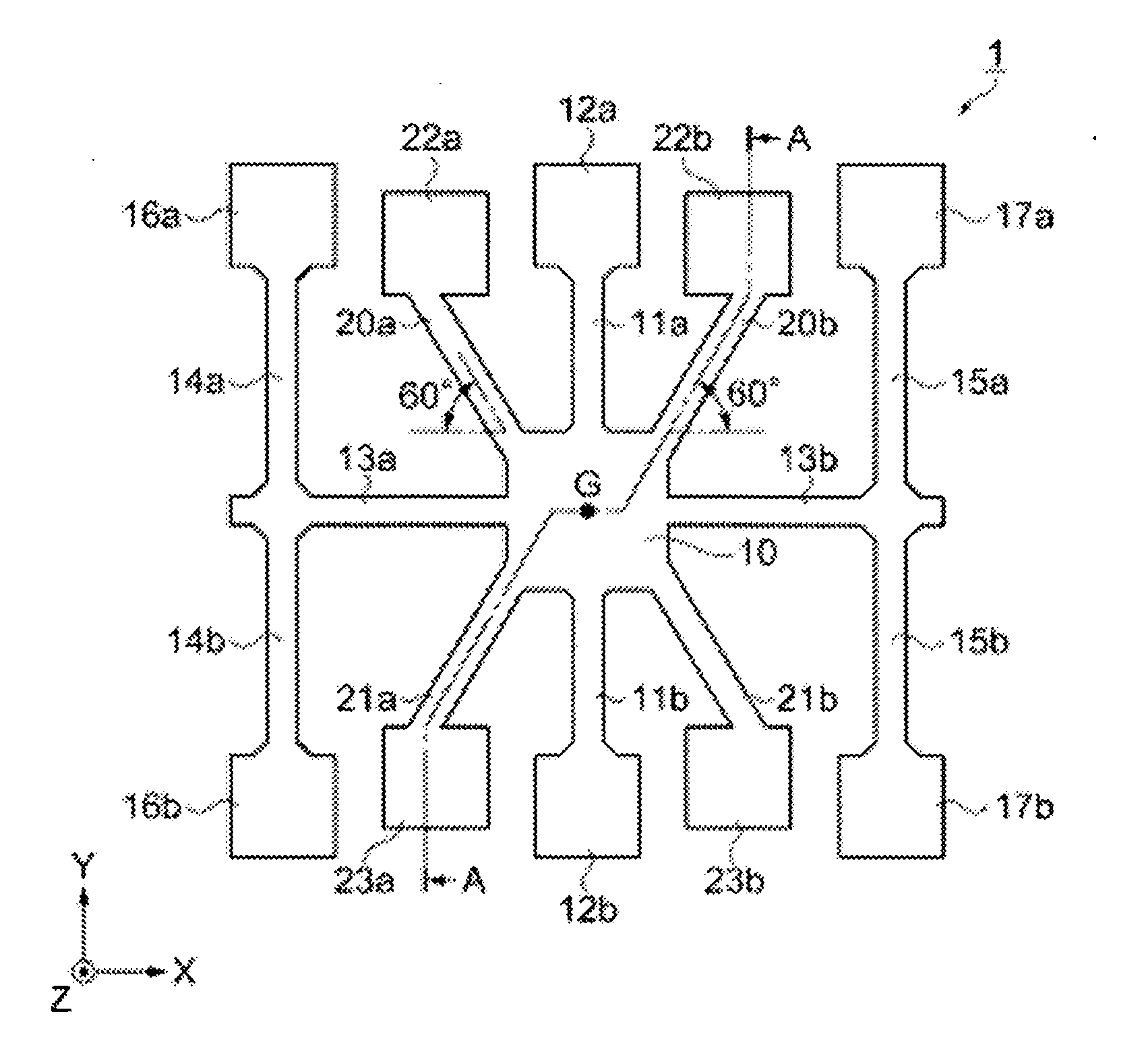
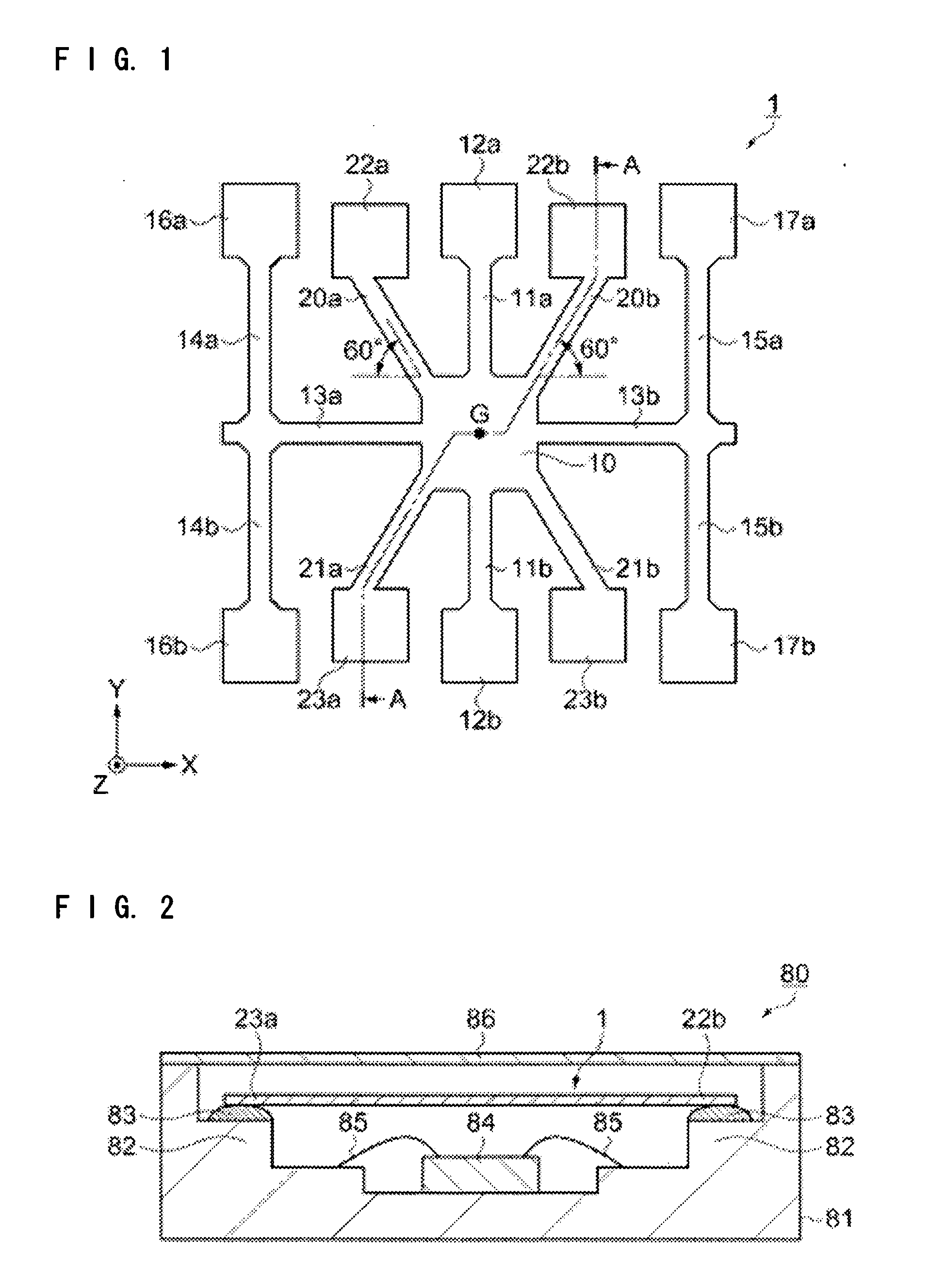
[0046]FIG. 1 is a plan view schematically illustrating a piezoelectric vibration gyro element according to an embodiment.

[0047] The piezoelectric vibration gyro element is formed by etching a Z-plate of quartz, utilizing a photolithography technology. The quartz has an X-axis called an electric axis, a Y-axis called a mechanical axis and a Z-axis called an optical axis. The Z-plate is a quartz substrate having a thickness in the direction of the Z-axis and having a flat surface on the XY plane.

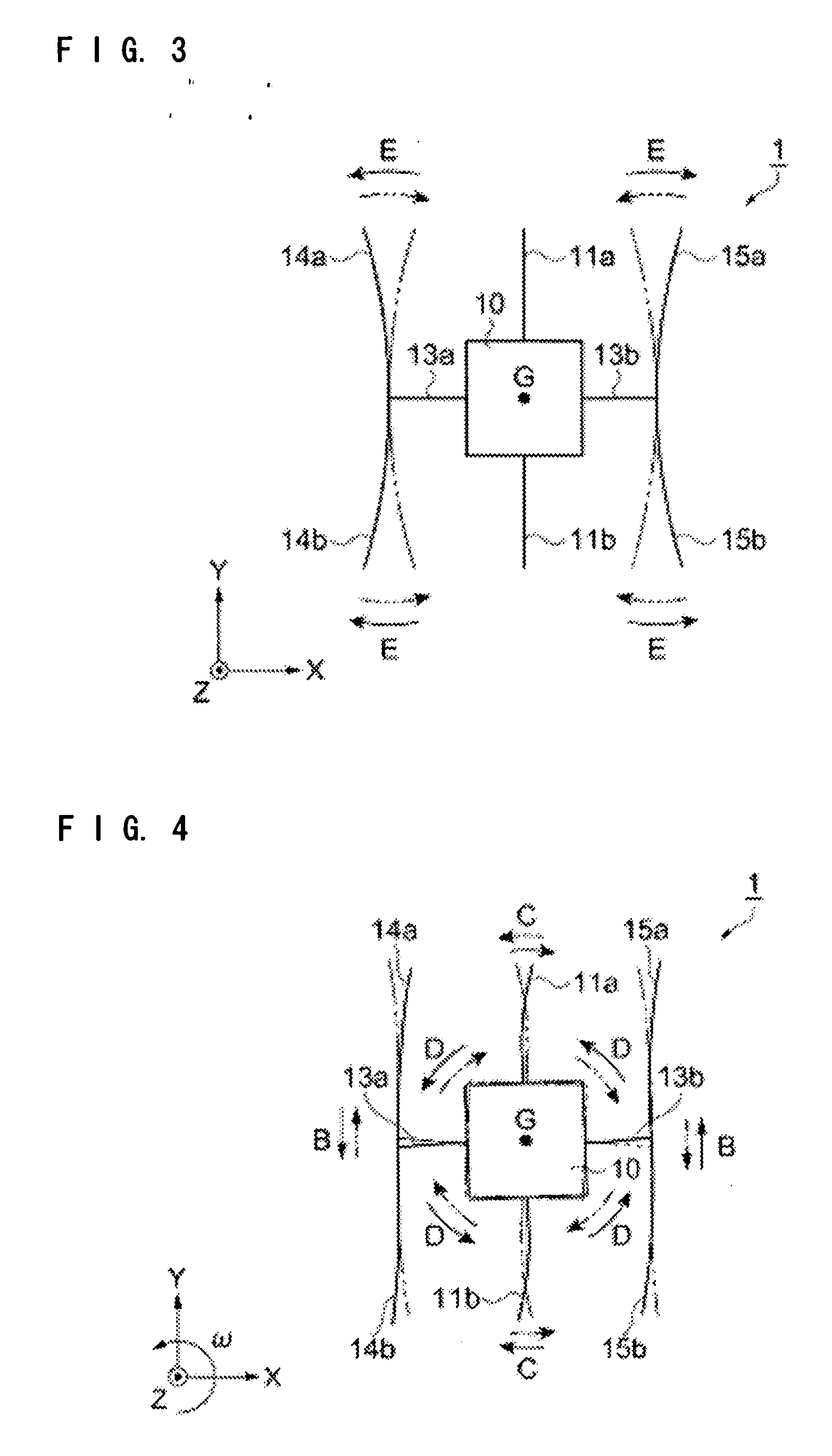
[0048] The piezoelectric vibration gyro element 1 includes a pair of vibration detection arms 11a and 11b linearly extending from the base portion 10, one upward in the diagram and one downward, a pair of coupling arms 13a and 13b extending to the right and left from the base portion 10 at right angles with the vibration detection arms 11a and 11b, and right and left pairs of vibration driving arms 14a,...


PUM


Abstract

A piezoelectric vibration gyro element formed by etching from a quartz substrate of a Z-plate, includes: a base portion, a pair of vibration arms for detection extending from the base portion toward both sides thereof in the direction of Y-axis, a pair of coupling arms extending from the base portion toward both sides thereof in the direction of X-axis, pairs of vibration arms for driving extending from the end portions of the coupling arms toward both sides thereof in the direction of Y-axis, four beams extending from the base portion, and support portions connected to the ends of the beams, which are all arranged on an XY plane; wherein the beams are extending in the directions of about 30° or about 60° with the X-axis as a reference.

Description

BACKGROUND [0001] 1. Technical Field [0002] The present invention relates to a piezoelectric vibration gyro element formed by etching, to a structure for supporting the piezoelectric vibration gyro element and to a gyro sensor. [0003] 2. Related Art [0004] In recent years, there has been much used a gyro sensor incorporating a vibration gyro element in a container for correcting unintentional movement of the hands holding a camera device and for controlling the attitude of a mobile navigation system such as that used in a motor vehicle by using GPS satellite signals. [0005] As the vibration gyro element, there has been known a so-called double T-shaped gyro element in which, for example, a drive vibration system of nearly a T-shape is coupled to a base portion to which a vibration detection system is coupled (see JP-A-2001-12955, FIG. 1). The double T-shaped gyro element adheres to and supports the base portion, and detects angular velocity. In order to improve the supporting streng...

Claims


Application Information

Patent Timeline
Patent Type & Authority Applications(United States)
IPC IPC(8): G01P15/08G01C19/56G01C19/5621G01C19/5628
CPCG01C19/5607
Inventor OGURA, SEIICHIRO
Owner SEIKO EPSON CORP
Why Eureka
Try Eureka