Method for detecting reverse rotation for internal combustion engines

a technology of internal combustion engine and reverse rotation, which is applied in the direction of machines/engines, electrical control, instruments, etc., can solve the problems of engine rotation in reverse, sampling of crankshaft signals, and unsatisfactory reverse rotation of crankshafts

Inactive Publication Date: 2006-07-27
ROBERT BOSCH GMBH
View PDF25 Cites 33 Cited by
  • Summary
  • Abstract
  • Description
  • Claims
  • Application Information

AI Technical Summary

Benefits of technology

[0013] In the event of reverse rotation of the crankshaft, the injection and/or ignition is/are preferably suppressed, preventing the engine from rotating in reverse. In addition, in the event of reverse rotation of the crankshaft, injection and/or ignition may remain suppressed until the crankshaft attains a minimum rotational speed in the forward direction of rotation.
[0014] In the event of a signal level change of one of the sensors, a counter in the control unit for the crankshaft angle is preferably incremented or decremented as a function of the direction of rotation. The absolute crankshaft angle is thus known at all times. The instantaneous crankshaft speed may be additionally determined from these values by determining the tooth time between two edges

Problems solved by technology

One problem when starting the engine is an undesirable reverse rotation of the crankshaft.
Once the engine rotates in reverse, if the reverse rotation is not detected, the correct assignment of injection and ignition for the engine controller is disrupted, causing the engine to rotate in reverse for a certain time.
The basic problem is that samplin

Method used


Image

  • Method for detecting reverse rotation for internal combustion engines
  • Method for detecting reverse rotation for internal combustion engines
  • Method for detecting reverse rotation for internal combustion engines

Examples


Embodiment Construction

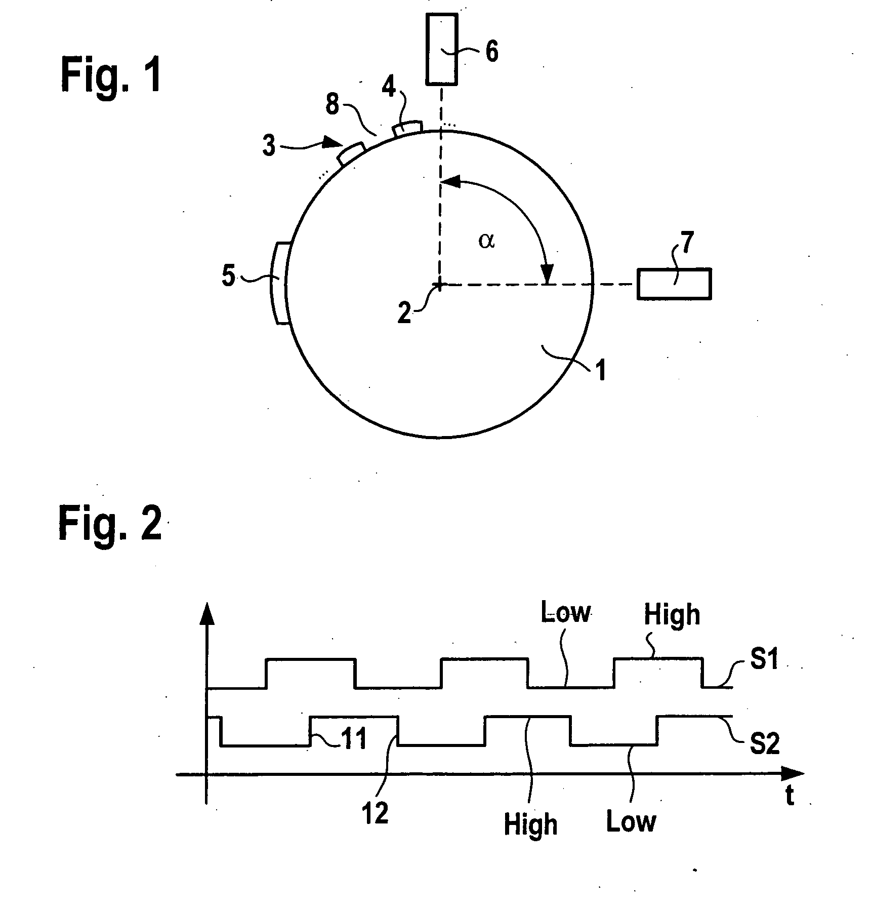
[0020]FIG. 1 shows a schematic drawing of a sensor disk 1, which is situated directly on a crankshaft or camshaft, for example, or is indirectly connected to the camshaft with the aid of transmission elements for rotation. Sensor disk 1 rotates about an axis 2. Markings 3 are situated on the outer periphery of sensor disk 1. The markings include, for example, teeth 4, which are situated equidistant over the outer periphery of sensor disk 1. Tooth spaces 8 are situated between teeth 4. An additional marking 5, for example, as shown here in the form of a tooth 4 having double the width or in the form of a larger tooth space between two teeth 4 or the like marks an established zero position of the crankshaft. Each tooth extends over an angle of approximately 3°; each tooth space extends over an angle of 3°. Therefore, tooth 4 and the adjacent tooth space 8 extend over an angle of approximately 6°.

[0021] A first sensor 6 and a second sensor 7 are situated on sensor disk 1. Sensors 6, 7...


PUM


Abstract

In a method for detecting reverse rotation when starting an internal combustion engine having a sensor disk which is coupled to a crankshaft of the engine, the sensor disk having a marking via an alternating arrangement of teeth and tooth spaces, and a first sensor and a second sensor each capable of generating an electric signal which may assume at least two signal levels, being associated with the sensor disk, one of the signal levels being associated with a tooth and the other signal level with a tooth space, a rising or falling signal edge of the one signal and the signal level of the other signal being used for determining the direction of rotation and increment of the angle of rotation of the crankshaft, the start characteristics are improved by determining the direction of rotation during the start of the engine as early as at the first signal edge.

Description

FIELD OF THE INVENTION [0001] The present invention relates to a method for detecting reverse rotation at the start of an internal combustion engine having a sensor disk which is coupled to a crankshaft of the engine, the sensor disk having a marking via an alternating arrangement of teeth and tooth spaces, and a first sensor and a second sensor being associated with the sensor disk, each being capable of generating an electric signal which may assume at least two levels, one signal level being associated with a tooth and the other with a tooth space, a rising or falling signal edge of one signal and the signal level of the other signal being used for determining the direction of rotation and increment of the rotational angle of the crankshaft, as well as to a control unit for carrying out the method. BACKGROUND INFORMATION [0002] One problem when starting the engine is an undesirable reverse rotation of the crankshaft. Typical reasons for reverse rotation may be the movement of the...

Claims


Application Information

Patent Timeline
IPC IPC(8): F02D41/22F02P11/00G01M15/06
CPCF02D41/009F02D2250/06
Inventor KASSNER, UWE
Owner ROBERT BOSCH GMBH
Why Eureka
Try Eureka