
Cleaning chuck in situ

a technology of in situ cleaning and chucks, applied in the field of in situ cleaning of chucks, to achieve the effect of facilitating separation from polymer

Inactive Publication Date: 2006-07-27
NIKON CORP
View PDF8 Cites 51 Cited by
  • Summary
  • Abstract
  • Description
  • Claims
  • Application Information

AI Technical Summary

Benefits of technology

[0007] The present invention takes advantage of developments in the field of imprint lithography, which in turn relate to experience in the fields of stamping and embossing of plastics. In one version of imprint lithography, a wafer is coated with a liquid photopolymer and a transparent die is impressed into it. The photopolymer is then exposed to light of an appropriate wavelength through the die so that it becomes a solid. The die is then removed, leaving a polymer surface patterned with the features on the die surface. In other versions, the polymer is a solid initially, and combinations of pressure and heat are used to imprint the surface. Similar methods are used in the commercial process of stamping CDs. The important point is that the die pulls cleanly away from the polymer, with no residue from the polymer remaining on it, even if the die has very fine features on its surface. In fact, it has been reported that dies which initially are contaminated with particles or other buildup become cleaner as they repeatedly stamp polymer films. In imprint lithography, the die is coated with a very thin mold release layer to facilitate separation from the polymer.
[0008] Embodiments of the present invention provide a method and an apparatus for in situ chuck cleaning, which advantageously reduces downtime to restore flatness. A cleaning film is provided on a substrate such as a dummy reticle, and brought into contact with the surface of the chuck to remove any particles or material buildup from the chuck surface in situ. The cleaning film is deformable, and preferably softer than the particles or material to be removed from the chuck surface. The cleaning film may have some of the similar characteristics as films used in imprint lithography. For instance, the cleaning film may be made of a polymer material which can be heated to improve its ability to embed the particles or material to be removed.

Problems solved by technology

In fact, it has been reported that dies which initially are contaminated with particles or other buildup become cleaner as they repeatedly stamp polymer films.

Method used


Image

  • Cleaning chuck in situ
  • Cleaning chuck in situ
  • Cleaning chuck in situ

Examples


Embodiment Construction

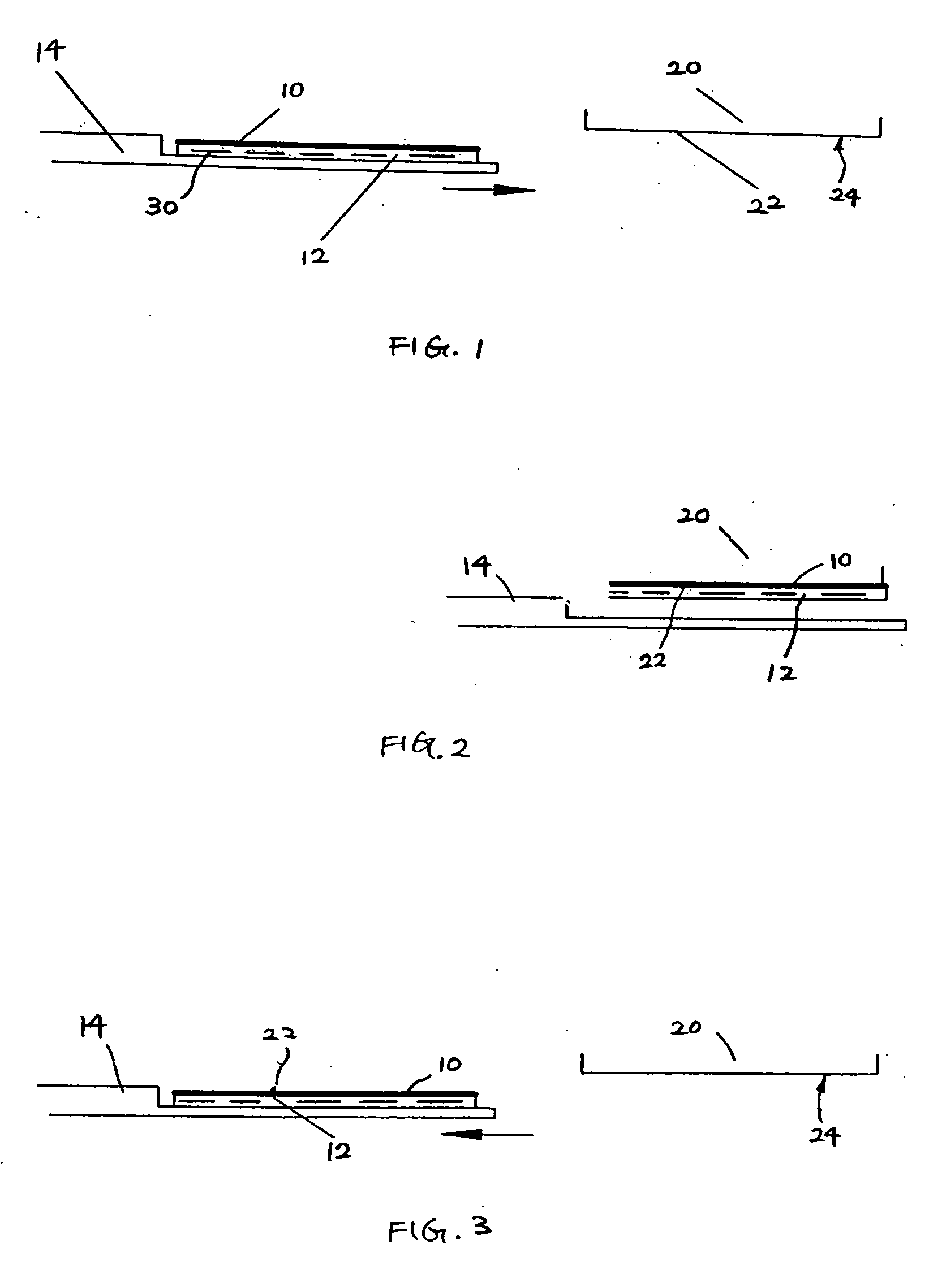
[0022]FIG. 1 shows a cleaning film or layer 10 disposed on a substrate such as a “dummy” reticle 12 which is placed on a transport mechanism such as an end effector 14. The cleaning film 10 may be provided on the substrate 12 by forming thereon or attaching thereto using any suitable technique, including deposition, molding, plating, bonding, joining, and the like. The end effector 14 may be one that is normally used to deliver an actual process reticle to the chuck for clamping. FIG. 1 shows a chuck 20 with a particle 22 disposed at the bottom surface 24 thereof.

[0023] In FIG. 2, the end effector 14 moves the dummy reticle 12 with the cleaning film 10 below the bottom surface 24 of the chuck 20, and the dummy reticle 12 is clamped to the chuck 20 with the cleaning film 10 placed in contact with the bottom surface 24 of the chuck 20. If the chuck 20 is an electrostatic chuck, the electrostatic clamping feature may be activated to clamp or press the dummy reticle 12 with the cleanin...


PUM


Abstract

Embodiments of the invention provide a method and an apparatus for in situ chuck cleaning, which advantageously reduces downtime to restore flatness. In one embodiment, a method of cleaning a chuck in situ comprises providing a cleaning layer on a substrate, the cleaning layer comprising a deformable material; positioning the substrate to place the cleaning layer in contact with a chuck surface of the chuck in situ, the chuck surface having thereon a material to be removed from the chuck surface; pressing the cleaning layer against the chuck surface with a sufficient pressure to allow the material on the chuck surface to be attached to the cleaning layer; and removing the substrate with the cleaning layer and the material attached thereto from the chuck.

Description

CROSS-REFERENCES TO RELATED APPLICATIONS [0001] This application is based on and claims the benefit of U.S. Provisional Patent Application No. 60 / 646,051, filed Jan. 21, 2005, the entire disclosure of which is incorporated herein by reference.BACKGROUND OF THE INVENTION [0002] The present invention relates generally to cleaning chucks and, more particularly, to methods and apparatus for in situ cleaning of chucks such as electrostatic chucks used in lithography systems. [0003] An exposure apparatus is one type of precision assembly that is commonly used to transfer images from a reticle onto a semiconductor wafer during semiconductor processing. A typical exposure apparatus includes an illumination source, a reticle stage assembly that retains a reticle, an optical assembly (sometimes referred to as a projection lens), a wafer stage assembly that retains a semiconductor wafer, a measurement system, and a control system. The resist coated wafer is placed in the path of the radiation ...

Claims


Application Information

Patent Timeline
Patent Type & Authority Applications(United States)
IPC IPC(8): B08B3/12B08B7/00B08B6/00B08B3/00
CPCB08B7/0014G03F7/70925
Inventor SOGARD, MICHAEL
Owner NIKON CORP
Learn More