Apparatus for trapping residual products in semiconductor device fabrication equipment

Inactive Publication Date: 2006-07-27
SAMSUNG ELECTRONICS CO LTD
View PDF8 Cites 19 Cited by
  • Summary
  • Abstract
  • Description
  • Claims
  • Application Information

AI Technical Summary

Benefits of technology

[0012] One object of the present invention is to provide an apparatus that prevents pressure loss in a process chamber in which a process is carried out in a vacuum.
[0013] Another object of the present invention to provide an apparatus that prevents the introduction of gaseous products, which could sol

Problems solved by technology

In particular, a large amount of the gaseous by-product transforms into powder due to an increase in pressure and drop in temperature that occurs while the gaseous by-product is being exhausted from the process chamber by an exhaust system of the LPCVD equipment.
Therefore, it clings to an exhaust line or a vacuum pu

Method used


Image

  • Apparatus for trapping residual products in semiconductor device fabrication equipment
  • Apparatus for trapping residual products in semiconductor device fabrication equipment
  • Apparatus for trapping residual products in semiconductor device fabrication equipment

Examples


first embodiment

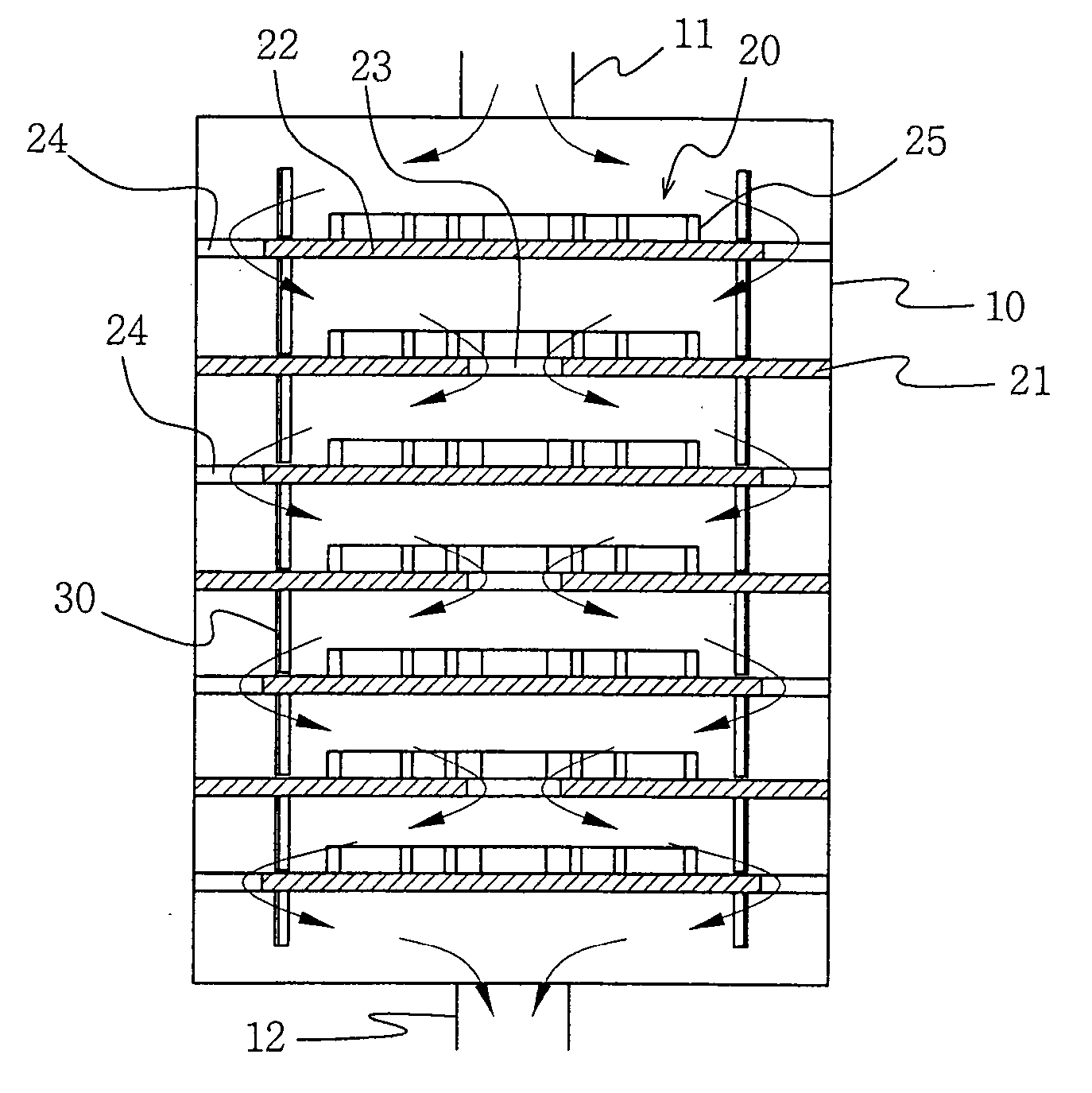
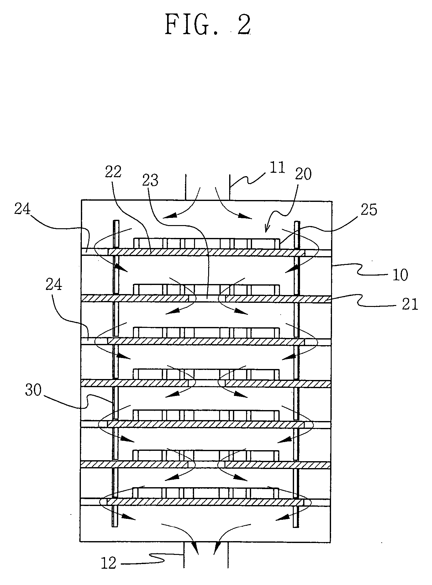
[0046] Also, as was the case with the first embodiment, an inert gas feeding line 600 (FIG. 5) can be connected to a leading end of the housing 100 or to the exhaust line 110 leading from the process chamber. Accordingly, an inert gas such as N2, He or Ar can be introduced into the housing 100 along with the gas exhausted from the process chamber to raise the pressure in the housing 100.

[0047] The present invention is devised to substantially transform the gaseous products exhausted from the process chamber into powder by providing a low temperature atmosphere for the gaseous products. The powder thus formed will adhere to the cooling members 20, 200 inside the housing 10, 100, thereby preventing powder from forming in or flowing into the exhaust line 12, 120 and the vacuum pump.

[0048] The invention operates as follows.

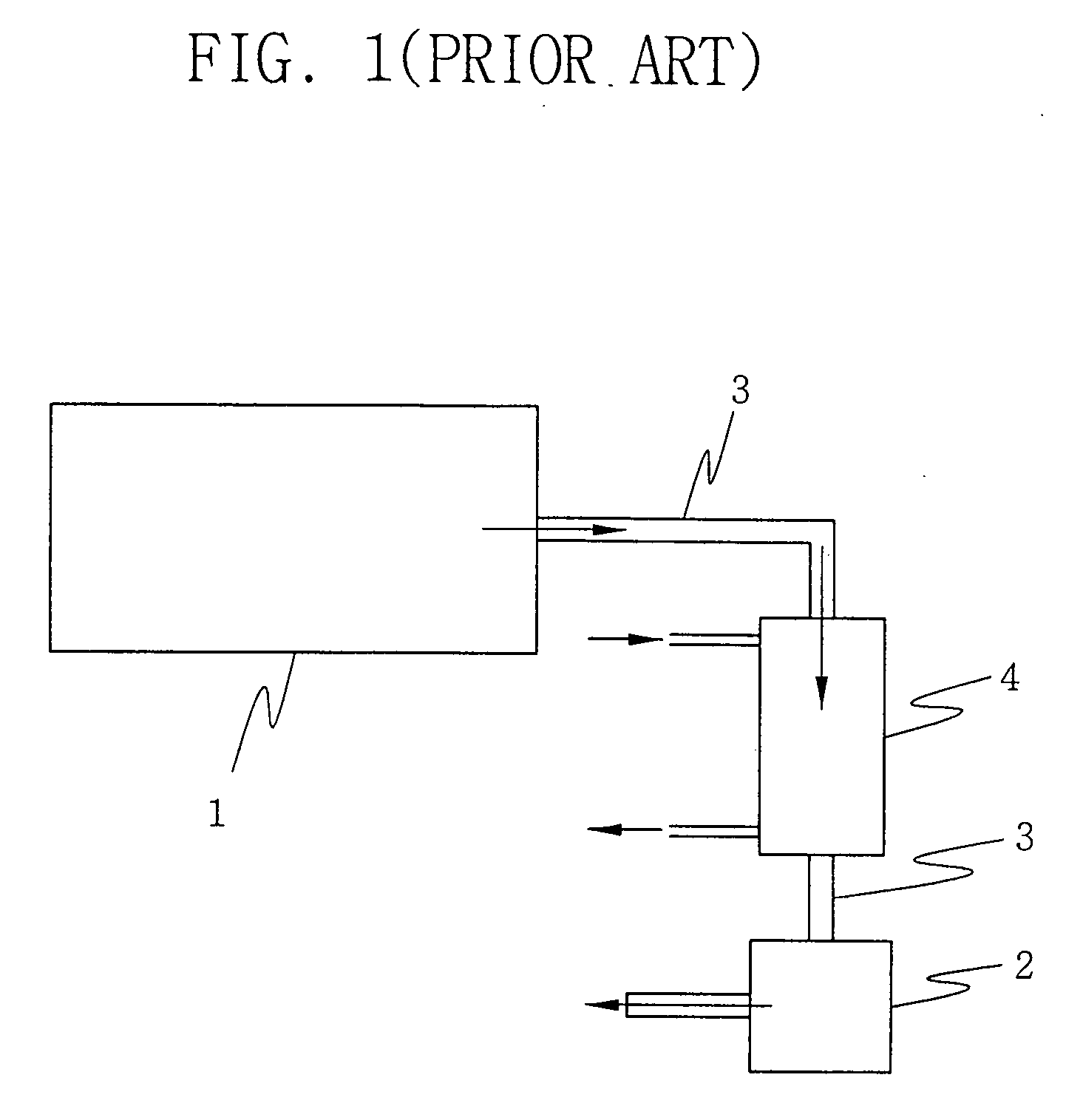
[0049] Various gaseous products are exhausted from the process chamber through the exhaust line 11, 110 by the operation of the vacuum pump. The gaseous products ar...

second embodiment

[0051] Therefore, the gaseous products introduced into the housing 10, 100 contact and undergo a heat exchange with the first and second cooling plates 21, 210 and 22, 220 inside the housing 10, 100. In the second embodiment, the gaseous products are rapidly cooled by refrigerant flowing through the cooling pipes 270 enclosed in the bases of the first and second cooling plates 210 and 220.

[0052] This transforms the gaseous products into powder, which is highly adhesive, inside the housing 10, 100. The powder thus clings to the first cooling plates 21, 210 and the second cooling plates 22, 220. Then, any remaining gas is exhausted to the outside via the exhaust line 12, 120. Furthermore, according to the invention, inert gas such as N2, He or Ar is fed through the feeding line 40, 600 into the housing 10, 100 to raise the pressure inside the housing 10, 100 and thus more promote the solidification of the gaseous products.

[0053] As described above, the present invention prevents thos...


PUM

PropertyMeasurementUnit
Pressureaaaaaaaaaa

Abstract

An apparatus traps residual products before the products can be formed in or flow to a vacuum pump in semiconductor device manufacturing equipment. The apparatus is connected between a process chamber and the vacuum pump and includes first and second cooling plates alternately disposed inside a hollow cylindrical housing. The first cooling plates each have a base and a grid projecting from a surface of the base, and define a vent hole extending through a central portion of the base. Each of the second cooling plates have a base and a grid projecting from a surface of the base, and define a plurality of vent holes extending through an outer peripheral portion of the base. Gaseous products flowing from a process chamber and through the housing are transformed into powder that adheres to the cooling plates.

Description

BACKGROUND OF THE INVENTION [0001] 1. Field of the Invention [0002] The present invention relates to semiconductor device manufacturing equipment. More particularly, the present invention relates to semiconductor device manufacturing equipment having a process chamber, and an exhaust system that evacuates the process chamber and exhausts gaseous products from the process chamber. [0003] 2. Description of the Related Art [0004] A semiconductor device is generally fabricated in part by forming a thin film on a substrate, and selectively etching the thin film to form a desired specific pattern on the substrate. These main processes are carried out in a low pressure and high temperature process atmosphere maintained within a so-called process chamber. In particular, the substrate is supported within the process chamber. Then, a reactant gas is injected into the process chamber and an RF power is applied to excite the gas. As a result, a chemical reaction is facilitated that forms a spec...

Claims


Application Information

Patent Timeline
IPC IPC(8): H01L21/306C23C16/00
CPCB01D5/0015B01D8/00C23C16/4412F04B37/06H01L21/02
Inventor PARK, JIN-JUN
Owner SAMSUNG ELECTRONICS CO LTD
Why Eureka
Try Eureka