Heat exchanger assembly

a technology of heat exchanger and assembly, which is applied in the direction of heat exchange apparatus, stationary tubular conduit assembly, stationary conduit assembly, etc., can solve the problems of microchannels imposing a significant increase in pressure drop over more conventional flow channels, inability to transfer heat necessary for certain applications, and correspondingly high pressure drop in working fluids. achieve the effect of increasing the effective surface area, reducing pressure drop, and increasing frontal area

Inactive Publication Date: 2006-07-27
INT MEZZO TECH
View PDF1 Cites 51 Cited by
  • Summary
  • Abstract
  • Description
  • Claims
  • Application Information

AI Technical Summary

Benefits of technology

[0010] The current invention extends the utility of these thin panel designs by providing multiple orientations and other options which serve to increase the effective surface area without necessarily increasing the frontal area of the heat exchanger system.
[0011] For instance, a typical thin panel heat exchanger is oriented so that its shortest flow channels are parallel to the approaching external fluid flow (the impinging flow). This is intended to minimize the pressure drop for that external fluid. The current invention, however, contemplates a thin panel heat exchanger inclined so that the approaching external fluid flow is no longer parallel to the fluid channels in the panel. With an inclined panel, the ratio of surface area to frontal area increases dramatically.
[0012] Experimentation has proven that a thin panel of the sort contemplated by the inventions discussed above may be inclined eighty (80) degrees from perpendicular with no appreciable effect on pressure drop. If a system is amenable to some pressure drop, the thin panels may be inclined to eighty five (85) degrees from perpendicular.
[0013] Experimentation has also proven that inclination of such a panel does not adversely affect the heat transfer properties of the panel, assuming the eventual configuration of headers, manifolds or other components assures proper distribution of fluid through both the internal and external channels.

Problems solved by technology

Until recently, such a heat exchanger was incapable of transferring the amounts of heat necessary for certain applications, such as an automobile.
Unfortunately, the small features which allow for high heat transfer create correspondingly high pressure drops in the working fluids.
Microchannels necessarily impose a significant increase in pressure drop over more conventional flow channels.

Method used


Image

  • Heat exchanger assembly
  • Heat exchanger assembly
  • Heat exchanger assembly

Examples


Embodiment Construction

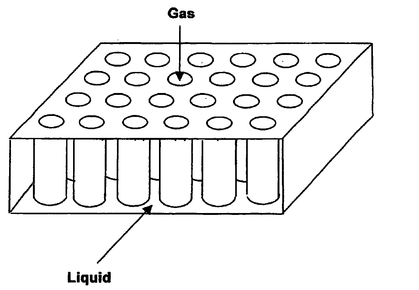
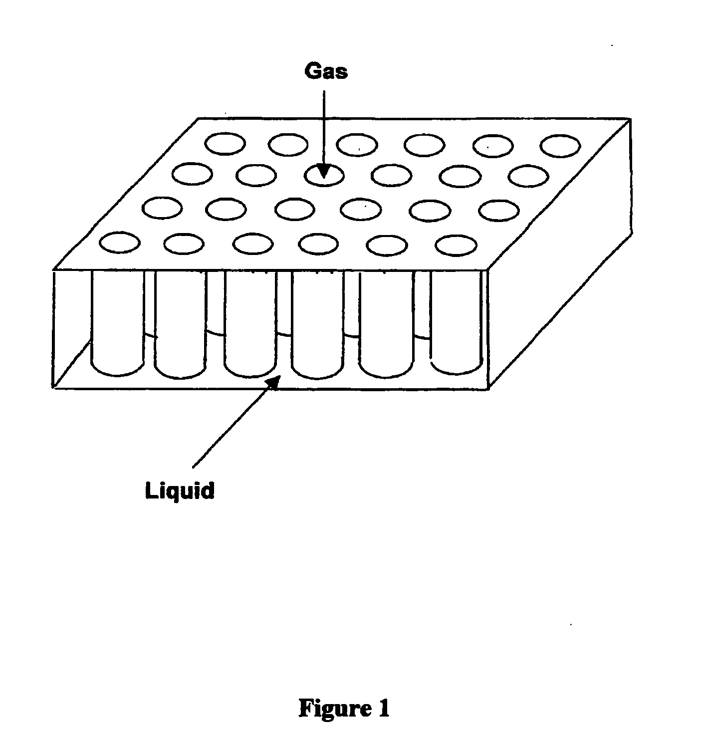
[0024] A schematic illustration of an embodiment of a thin panel heat exchanger is shown in FIG. 1 (not drawn to scale). In FIG. 1, the circular tubes are flow paths for a hot gas. The broad faces of the thin panel provide one large channel for the liquid flow path. This liquid flow path is broken up by the multitude of circular tubes. This arrangement creates a relatively large amount of primary surface area for heat transfer between the two fluids.

[0025] The flat panel illustrated in FIG. 1 is only an example of a thin panel heat exchanger. Any heat exchanger which has a shortest fluid flow channel less than 2.0 cm can be used to take advantage of the current invention.

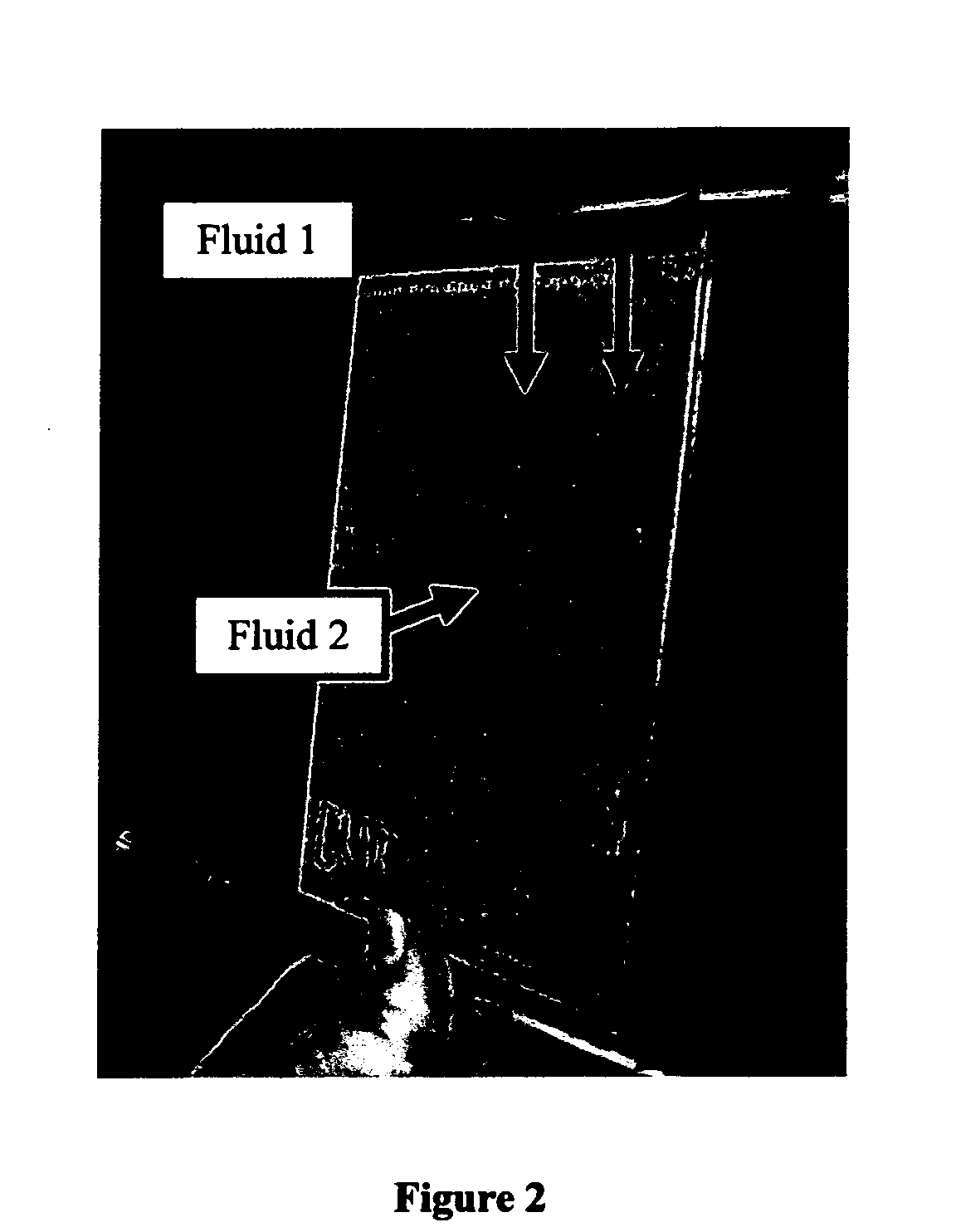
[0026]FIG. 2 is a picture of a thin panel heat exchanger made part of a heat exchanger system which delivers coolant to the panel through tubes. Each tube has a slot in which the panel may be mounted. The panel is brazed or otherwise fixedly connected to the tubes. Fluid 1, typically the coolant, is delivered to t...


PUM


Abstract

An apparatus providing high efficiency heat exchange between two fluids is disclosed. The apparatus most commonly comprises multiple thin panels with fluid channels directing the flow of the two fluids, specifically: one or more flat panels aligned at some angle to the flow of the fluid traveling through the shortest channel of the thin panels. The panels are arranged in series and parallel, so that the hot fluid travels through multiple thin panels. The coolant is delivered to the thin panels through tubes or manifolds while the hot fluid is delivered through a duct or other piping.

Description

REFERENCE TO RELATED APPLICATIONS [0001] This Application is a continuation-in-part of co-pending application identified as U.S. patent application Ser. No. 11 / 041,767, filed Jan. 24, 2005, the disclosure of which is incorporated herein by reference.FIELD OF THE INVENTION [0002] The present invention relates to heat exchangers, particularly very high efficiency heat exchangers and heat exchanger systems. SUMMARY OF THE INVENTION [0003] Heat exchangers are used in a great many mechanical and electrical systems. Some of the most commonly known applications include the condenser of a refrigerator or the radiator of an automobile. Increasingly, customers have demanded high efficiency heat exchangers for cooling computer chips and other electronic components. This demand, among others, produces a continuing need for increased efficiency in a smaller volume. [0004] Compact heat exchangers are used in applications which demand low overall mass or weight. Until recently, such a heat exchang...

Claims


Application Information

Patent Timeline
Patent Type & Authority Applications(United States)
IPC IPC(8): F28D1/00
CPCF28D7/0008F28D7/1615F28F7/02
Inventor KELLY, KEVIN W.LUKE, PATRICK S.MCCOY, KEVIN P.
Owner INT MEZZO TECH
Why Eureka
Try Eureka