Chiral nematic liquid crystal composition, liquid crystal display device, and production method thereof

a liquid crystal composition and chiral nematic technology, applied in the direction of thin material processing, instruments, chemistry apparatus and processes, etc., can solve the problems of insufficient contrast between the “bright” and “dark” states of the display device above, and achieve the effect of reducing the weight of the device, superior visibility, and effective suppression of damag

Inactive Publication Date: 2006-07-27
KONICA MINOLTA INC
View PDF4 Cites 4 Cited by
  • Summary
  • Abstract
  • Description
  • Claims
  • Application Information

AI Technical Summary

Benefits of technology

[0020] The liquid crystal display device using the chiral nematic liquid crystal composition according to the invention has a sufficient contrast between the “bright” state (e.g., PL state) and the “dark” state (e.g., FC or Homeo state) and thus is superior in visibility.
[0021]FIG. 1 is a schematic view illustrating the cross-sectional structure of the liquid crystal display device in an embodiment of the invention. The liquid crystal display device shown in FIG. 1 has a structure wherein a liquid crystal composition 11 is put and held between a pair of substrates 1 and 2 respectively having electrodes 3 and 4. In FIG. 1, transparent electrodes 3 and 4 in the shape of multiple belts mutually in parallel are formed respectively on the surfaces of the substrates 1 and 2. The transparent electrode 3 and the transparent electrode 4 are placed as they face each other and the belts are in the directions perpendicular to each other. An insulating thin film 5 is coated on each of the electrodes 3 and 4. An orientation film 7 is formed additionally on the insulating thin film 5. The numeral 10 represents a polymer structure serving both as a spacing part and an adhesive part connecting the substrates, while the numeral 13 is a spacer serving similarly as a spacing part. The numeral 12 represents a sealing material enclosing the liquid crystal composition 11 inside the cell. A black visible light-absorbing layer 9 is formed as needed on the outer face (rear face) of the substrate 2 opposite to the incident light-side. Alternatively, a substrate 2 inherently absorbing visible light may be used instead of forming the visible light-absorbing layer 9.
[0022] Hereinafter, main components for the liquid crystal display device will be described in detail.
[0023] In FIG. 1, both substrates 1 and 2 have light-transmitting property, but of a pair of substrates for use in the liquid crystal display device, at least one substrate (at least, incident-side substrate 1) should have light-transmitting property. Examples of the substrates having light-transmitting property inc

Problems solved by technology

However, the contrast between the “bright” and “dark” stat

Method used


Image

  • Chiral nematic liquid crystal composition, liquid crystal display device, and production method thereof
  • Chiral nematic liquid crystal composition, liquid crystal display device, and production method thereof
  • Chiral nematic liquid crystal composition, liquid crystal display device, and production method thereof

Examples


example 1

[0094] A nematic liquid crystal (BL006; manufactured by Merck & Co., Inc., NI point=113° C., anisotropy of dielectric constant (Δε)=17.3, anisotropy of refractive index (Δn)=0.286) and a chiral agent (MLC6247; manufactured by Merck & Co., Inc.) were mixed. The amount of the chiral agent was determined in such a manner that the selective reflection wavelength (wavelength of the maximum peak in the spectral distribution curve when planar) becomes 580 nm. The ratio of liquid crystal / chiral agent was 64 / 36. The TCN-I of the chiral nematic liquid crystal obtained was 106° C.

[0095] Two parts of the gelling agent represented by the chemical formula (2) was added to 98 parts of the chiral nematic liquid crystal, and the mixture was mixed well to give a gelated chiral nematic liquid crystal composition A.

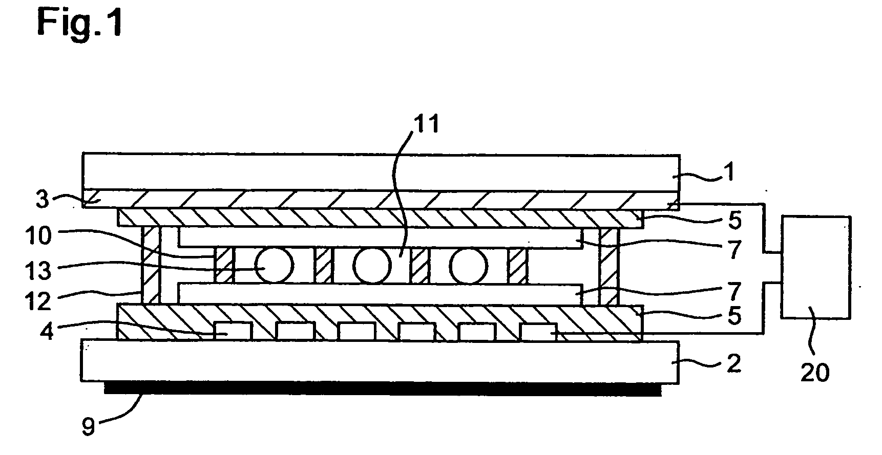
[0096] The display device shown in FIG. 1 (however, polymer structure and insulating thin film were eliminated) was prepared by using the gelated chiral nematic liquid crystal composition ...

example 2

[0103] A chiral nematic liquid crystal was obtained in a manner similar to Example 1, except that E44 (manufactured by Merck & Co., Inc., NI point=100° C., Δε=16.8, Δn=0.262) was used as the nematic liquid crystal. The ratio of nematic liquid crystal / chiral agent was 64 / 36 / . TCN-I of the chiral nematic liquid crystal obtained was 92° C.

[0104] Two parts of the gelling agent represented by chemical formula (2) was added to 98 parts of the chiral nematic liquid crystal, and the mixture was mixed well to give a gelated chiral nematic liquid crystal composition B.

[0105] A liquid crystal display device was obtained in a manner similar to Example 1, except that the gelated chiral nematic liquid crystal composition B was used and the temperature of the hot plate was set to 107° C. (TCN-I+15(° C.)).

example 3

[0106] A chiral nematic liquid crystal was obtained in a manner similar to Example 1, except that BL035 (manufactured by Merck & Co., Inc., NI point=96° C., Δε=16.6, Δn=0.260) was used as the nematic liquid crystal. The ratio of nematic liquid crystal / chiral agent was 64 / 36. TCN-I of the chiral nematic liquid crystal-obtained was 85° C.

[0107] Two parts of the gelling agent represented by chemical formula (2) was added to 98 parts of the chiral nematic liquid crystal, and the mixture was mixed well to give a gelated chiral nematic liquid crystal composition C.

[0108] A liquid crystal display device was obtained in a manner similar to Example 1, except that the gelated chiral nematic liquid crystal composition C was used and the temperature of the hot plate was set to 100° C. (TCN-I+15(° C.)).


PUM


Abstract

A chiral nematic liquid crystal composition, characterized in that a self-organizing type gelling agent is contained and the phase transition temperature between liquid crystal and isotropic phases is higher than the sol-gel transition temperature, a liquid crystal display device wherein the chiral nematic liquid crystal composition is put and held between a pair of substrates having an electrode, and a method for producing a liquid crystal display device wherein the chiral nematic liquid crystal composition is heated to a temperature of not lower than the phase transition temperature between liquid crystal and isotropic phases and then cooled down to room temperature.

Description

[0001] This application is based on application(s) No. 2005-019396 filed in Japan, the contents of which are hereby incorporated by reference. BACKGROUND OF THE INVENTION [0002] 1. Field of the Invention [0003] The invention relates to a chiral nematic liquid crystal composition, a liquid crystal display device, and the production method thereof. [0004] 2. Description of the Related Art [0005] Liquid crystal display devices employing a chiral nematic liquid crystal composition containing an added chiral agent in its nematic liquid crystal that is in the cholpesteric phase at room temperature have been known. Such liquid crystal display devices fundamentally have a chiral nematic liquid crystal composition put and held between a pair of substrates having a transparent electrode, and the display is performed by switching the liquid crystal between its planar (PL) state and the focal conic (FC) or homeotropic (Homeo) state while applying a high / low pulse voltage (driving voltage) betwe...

Claims


Application Information

Patent Timeline
IPC IPC(8): C09K19/52C09K19/36C09K19/02
CPCC09K19/02C09K19/54Y10T428/1036C09K2019/526Y10T428/10C09K2019/0492C09K2323/00C09K2323/03
Inventor IZUMI, TOMOO
Owner KONICA MINOLTA INC
Why Eureka
Try Eureka